33.3.4. Gas Force
A gas force is defined with two bodies. This entity is created between a cylinder (an engine block) and a piston. This force occurs at a firing angle.
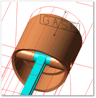
Figure 33.71 Gas Force
33.3.4.1. Modeling Options
Click the Gas icon of the Piston Connector group in the Piston tab. The user can see the Crank Component – Gas Force dialog box.
The user can select the position where the gas force is created in Component Index.
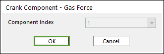
Figure 33.72 Crank Component - Gas Force dialog box
Click OK.
33.3.4.2. Properties
Click right mouse button on the gas force component to choose Properties of gas force. The user can modify the property of a gas force in the following dialog.
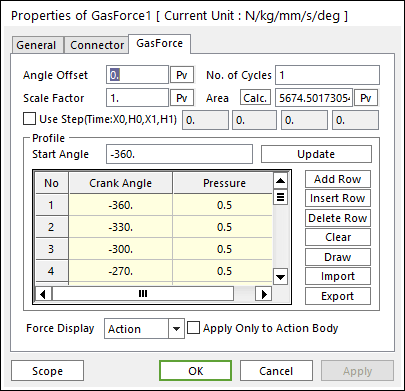
Figure 33.73 Gas force property page
Angle Offset: The user can offset angle about the gas force profile.
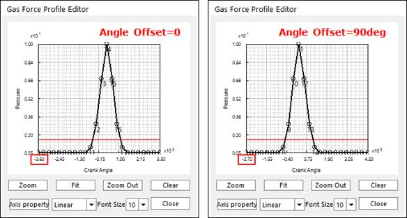
Figure 33.74 Example for Angle Offset
No. of Cycles: The user can give pressure once the inputted cycles.
Scale Factor: The user can give pressure of the gas force profile as \(\mathbf{\times}\mathbf{\ }\)Scale Factor.
Area: If the user clicks Calc., this value is set automatically.
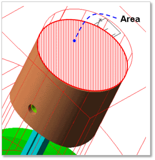
Figure 33.75 Area on which Gas Force acts
Use Step: The gas force can be applied as STEP function.
Profile: The user can modify a gas force profile using the profile grid. Also, RecurDyn/Crank offers some convenient method to modify the gas force profile. So, if the user clicks Draw, the Gas Force Profile Editor dialog is displayed on the screen. Also, the user can import or export the gas force profile data.
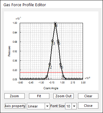
Figure 33.76 Gas Force Profile Editor dialog box
Applied on the Only Action Body: The gas force can be applied on the action body (usually piston) only.