32.3.5. Balancing Screw Coupler
A balancing screw coupler is defined between a crank shaft and a balancing shaft.
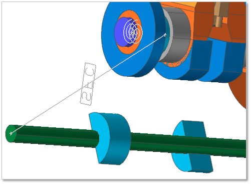
Figure 32.164 Balancing Screw Coupler
Balancing Screw Coupler Force
A screw coupler has the torque and reaction force value.
Torque
\(T_1=\left[ K(-Ratio \times \theta_1-\theta_2)+C(-Ratio \times \dot{\theta_1}-\dot{\theta_2})\right] \times Ratio\)
\(T_2=K(-Ratio \times \theta_1-\theta_2) + C(-Ratio \times \dot{\theta_1}-\dot{\theta_2})\)
- where, \(Ratio (\text{speed ratio}) = \frac{R_1}{R_2}(\text{Calculated Value})\)
\(\theta_1\) is an angle of Crank Shaft referred from body reference frame of EBlock.
\(\theta_2\) is an angle of Balancing Shaft referred from body reference frame of EBlock.
\(T_1\) is torque acting on a Crank Shaft
\(T_2\) is torque acting a Balancing Shaft
Reaction Force (Fx, Fy)
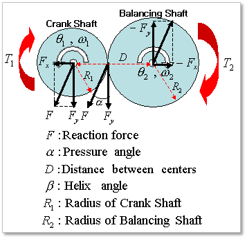
Figure 32.165 Balancing Screw Coupler Force
\(F_y=T_1/(D \times r / (r+1)) r=Ratio\)
\(F=F_y/ \cos(\alpha)\)
\(F_x=F \times \sin(\alpha)\)
\(F_y / \cos(\alpha)/ \sin(\alpha)\)
Reference
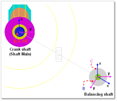
Figure 32.166 reference information
Screw coupler (Drive: Crank Shaft, Driven: Balancing Shaft)
The base marker between an Eblock (base) and a shaft main body (action) is the frame A
The action marker between an Eblock (base) and a shaft main body (action) is the frame C
The base marker between an Eblock (base) and a balancing shaft body (action) is the frame A
The action marker between an Eblock (base) and a balancing shaft body (action) is the frame C
The reference marker is the frame B
32.3.5.1. Modeling Options
Click the Couple icon of the Crank Connector group in the Crank tab. The user can see the dialog.
The user can select the position where Balancing Screw Coupler is created in Component Index.
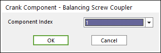
Figure 32.167 Crank Component - Balancing Screw Coupler dialog box
Click OK.
32.3.5.2. Properties
The user can modify the property of balancing screw coupler in the following dialog.
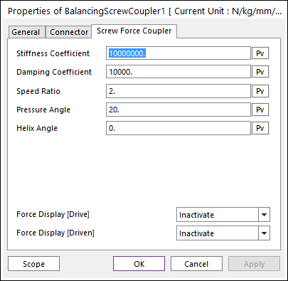
Figure 32.168 Balancing Screw Coupler property page
Stiffness Coefficient: Defines a stiffens coefficient for the screw force.
Damping Coefficient: Defines a damping coefficient for the screw force.
Speed Ratio: Defines a speed ratio between the crank shaft and the balancing shaft.
Pressure Angle: Defines a pressure angle between the crank shaft and the balancing shaft.
Helix Angle: Defines a helix angle between the crank shaft and the balancing shaft.