32. Crank

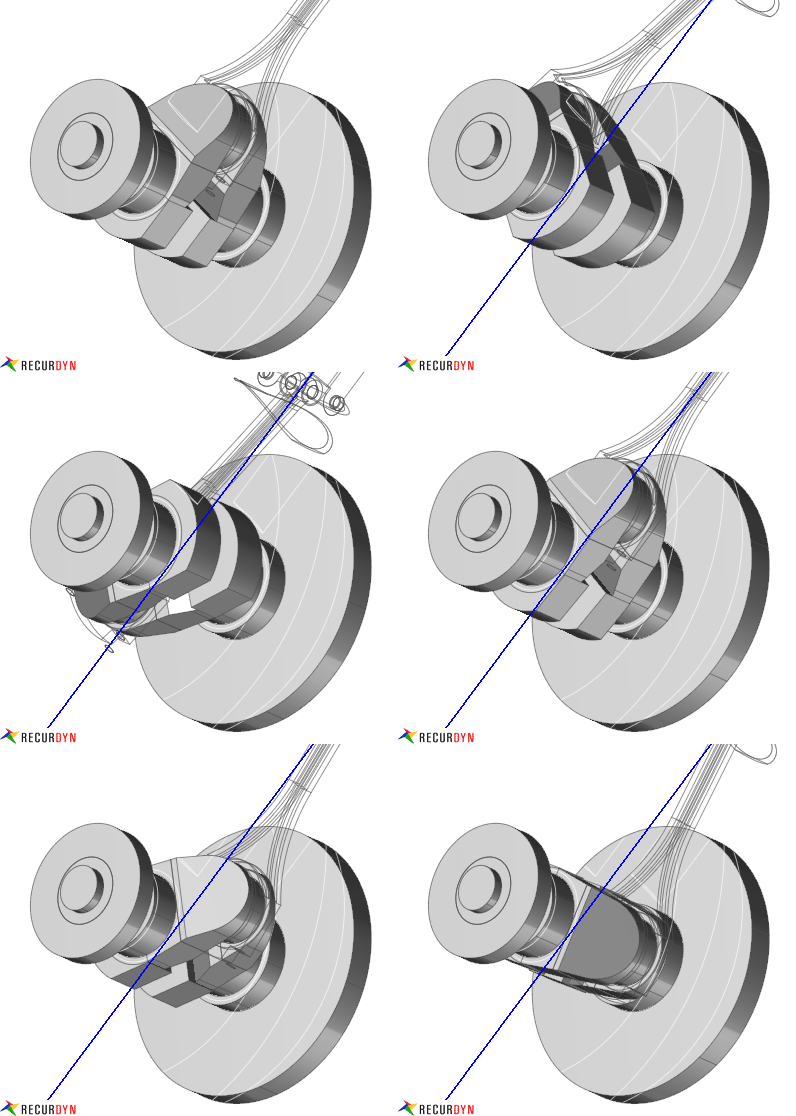
Figure 32.1 Crank example
RecurDyn/Crank consists of system builder, geometries, and
connecting elements. The user can create crank system easily using
system builder. Geometries such as engine block, crankshaft, conrod, piston pin, piston, flywheel, torsional damper, balancing shaft and
EDT can be created. Geometries are connected by connecting
elements such as bearing, engine mount, liner connector, gas force, and Balancing Screw Coupler.
After setting up a Pre-Global data and Global data, the
user can create components to structure Crank System using two
kinds of method. One is System Builder which is a method using
Component Builder. In the Component Builder dialog page, the
user can create components by selecting the geometries and connecting
elements the user needs to create. The other is Manual Builder,
which is a method to create components by clicking component icon one
by one in RecurDyn/Crank.
Step to Run Crank System
Define a pre-global data of an engine.
Define a global data of an engine.
Select geometries and connecting elements at Component Builder.
Define values of selected geometries and connecting elements.
Build up an engine model by clicking OK.
Run the simulation.
- 32.1. System Builder
- 32.2. Geometric Entities
- 32.3. Connecting Entities
- 32.4. CCMAV (Torque Control of Constant Mean Angular Velocity of a Crank-Shaft)
- 32.5. Contact Entities