31.3.3. Involute Analytic Contact
Involute analytic contact generates a force between spur and helical gear pair, including internal spur and internal helical gear.
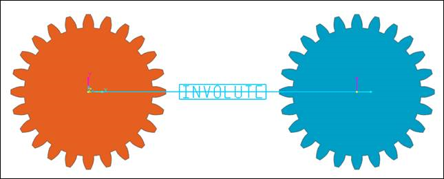
Figure 31.100 Involute Analytic Contact
Note
Involute Contact entity is supported for spur gear, helical gear, internal spur gear, and internal helical gear.
If points of Tooth Profile Editor in Gear Property Page are manually modified, edited shape is not considered in Involute Analytic Contact (Values defined in Geometry Data Page are used only).
31.3.3.1. Modeling Options
The user can define an Involute Analytic Contact as follows.
Body(Group), Body(Group)
Body(Group): Selects a bear gear.
Body(Group): Selects an action gear.
31.3.3.2. Properties
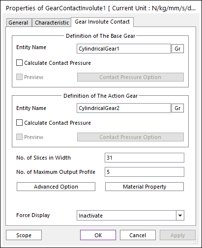
Figure 31.101 Gear Contact Involute property page [Gear Involute Contact page]
Calculate Contact Pressure: Contact pressure for gear tooth surface is calculated. Contour file is generated. Preview checkbox is activated when calculate contact pressure is checked.
Contact Pressure Option: Set the number of patches in involute profile and gear tooth thickness for contact pressure calculation and display.
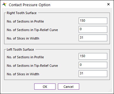
Figure 31.102 Contact Pressure Option dialog box
No. of Sections in Profile: Set the number of patches in involute profile.
No. of Sections in Tip-Relief Curve: Set the number of patches in tip relief curve. If no tip relief area, this number is ignored.
No. of Slices in Width: Set the number of slices (layers) in thickness direction. This number should be odd number. Note that the number of slices is different with the number of patches (# of patches = # of slices – 1).
Note
If you cannot see the contact pressure result in contour display, increase the number of sections in profile or tip-relief curve. This circumstances can occur when gear material properties are highly stiff, or contact forces are small (It means calculated Hertzian area is small compared to the patch size, so patch size should be decreased accordingly).

Figure 31.103 Contact pressure patch preview without tip relief curve (left) and with tip relief curve (right)
No. of Slices in Width: The number of thickness layers in thickness direction. Gaps between thickness layers are equally divided. This should be odd number to include the mid-surface of gear cross-section. This number is used in contact calculation
No. of Maximum Output Profile: Defines the number of max involute contact pairs for output. User can define this value from 1 to (Small value among the number of teeth of two gears * 2). This value only affects Force Display and RPLT data about contact points.
Advanced Option: Tooth flexibility option and contact force averaging method can be set.
Material Property: Material properties can be set which are used in gear flexibility calculation.
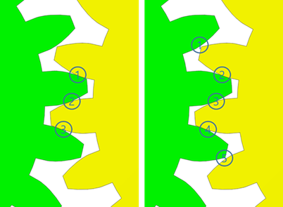
Figure 31.104 No. of maximum output profile contact pair is 3 and 5.
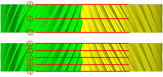
Figure 31.105 No. of slices in width is 3 and 5.
Advanced Option
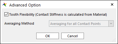
Figure 31.106 Advanced Option dialog box
Tooth Flexibility: Contact stiffness force is calculated with gear tooth flexibility theory.
Note
If tooth flexibility option is activated, stiffness coefficient in characteristic page is not considered in contact analysis. Contact force is calculated only by tooth stiffness factor and material properties.Also, Averaging Method is disabled when tooth flexibility option is activated. Averaging method is not considered in contact analysis when the tooth flexibility option is used.
Averaging Method: Accumulated contact forces are averaged with certain factor which is obtained from the number of contact points.
No Averaging option uses accumulated contact force directly.
Averaging for Each Pair option calculates partial sum of contact forces for each contact profile pair. And each partial sum is averaged with the number of contact points which are contained in that profile pair.
Averaging for all Contact Point option counts the total number of contact points and divides all contact forces with the total number.
Material Property
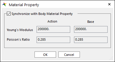
Figure 31.107 Material Property dialog box
Synchronize with Body Material Property: Get material properties from body data in RecurDyn or material data provided from KISSsoft. If checked, user-defined input is disabled.
31.3.3.2.1. Contact Characteristic
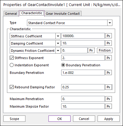
Figure 31.108 Gear Contact Involute property page [Characteristic page]
Type: Select a type as Standard Contact Force or User Contact Force.
Standard Contact Force: Defines the contact properties. (Refer to Characteristic Page for Geo Contact)
User Contact Force: Defines by the user written contact subroutine (Refer to Contact User Subroutine).
Maximum Penetration: Specifies the maximum penetration depth. Maximum penetration should be larger than zero. If calculated penetration in contact algorithm is larger than this value, it’s considered that contact is not occurred.
Maximum Step size Factor: The maximum step size is reduced by a factor of maximum step size factor.
31.3.3.3. Specialized Outputs
RPLT data of Gear Involute Contact is categorized in layer number and point number. Each layer represents thickness layer in gear rotational axis direction. Each point represents the contact point in profile pair number. Total layer number and total point number in each layer is matched with the number in contact property page. Also, contact forces and torques, and position data for gear pair is plotted. Force and torque are calculated from gear reference frame. Gear reference frame is defined as following rule: y-axis as the displacement vector from base gear center to action gear center, and z-axis as the rotating axis of base gear.
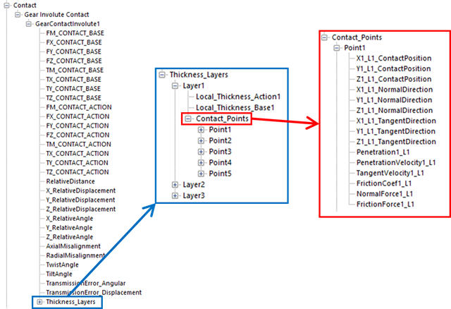
Figure 31.109 RPLT Data of Gear Involute Contact
X_RelativeDisplacement: Relative X displacement of action gear center to base gear center in gear ref. frame.
Y_RelativeDisplacement: Relative Y displacement of action gear center to base gear center in gear ref. frame.
Z_RelativeDisplacement: Relative Z displacement of action gear center to base gear center in gear ref. frame.
X_RelativeAngle: Yaw rotation (from Euler 321) of action gear from base gear.
Y_RelativeAngle: Pitch rotation (from Euler 321) of action gear from base gear.
Z_RelativeAngle: Roll rotation (from Euler 321) of action gear from base gear.
AxialMisalignment: Change of axial offset between current and initial action gear position from base gear position.
RadialMisalignment: Change of distance between base gear and action gear.
Twist: Definition of this value is the same as the twist used in meta model.
Tilt: Definition of this value is the same as the tilt used in meta model.
TransmissionError_Angular: If the gear pair does not make an ideal rotation, it is the value expression how much it is. it is calculated by
\[T{{E}_{ang}}=\left| \frac{{{z}_{1}}}{{{z}_{2}}} \right|{{\theta }_{g1}}+\alpha {{\theta }_{g2}}\]- Where,
- \({{z}_{1}},\,\,{{z}_{2}}\) are the number of teeth for gear1 and gear2 respectively.\({{\theta }_{g1}}\) is the rotation angle of gear1 and \({{\theta }_{g2}}\) is the rotation angle of gear2.\(\alpha\) has ‘1’ in the case of external gear and it has ‘-1’ in the case of internal gear.
TransmissionError_Displacement: If the gear pair does not make an ideal rotation, it is also the value expression how much it is. This value is widely used in gear analysis. it is calculated by
\[T{{E}_{disp.}}={{R}_{g1}}{{\theta }_{g1}}+\alpha {{R}_{g2}}{{\theta }_{g2}}\]Where, \({{R}_{g1}},{{R}_{g2}}\) are the number of base radius for gear1 and gear2 respectively. Other values are the same as them expressed in TransmissionError_Angular.
Each Layer RPLT structure contains the contact point data which is in that thickness layer.
Local_Thickness_Action: Thickness position of contact point in action gear center reference frame. Number in the end represents the layer number.
Local_Thickness_Base: Thickness position of contact point in base gear center reference frame. Number in the end represents the layer number.
Note
Number in the end represents the layer number.
Each Point RPLT structure contains the detailed information about each contact point.
X_L_ContactPosition: X position of contact point in global ref. frame.
Y_L_ContactPosition: Y position of contact point in global ref. frame.
Z_L_ContactPosition: Z position of contact point in global ref. frame.
X_L_NormalDirection: X component of contact unit normal vector in global ref. frame.
Y_L_NormalDirection: Y component of contact unit normal vector in global ref. frame.
Z_L_NormalDirection: Z component of contact unit normal vector in global ref. frame.
X_L_TangentDirection: X component of contact unit tangent vector in global ref. frame.
Y_L_TangentDirection: Y component of contact unit tangent vector in global ref. frame.
Z_L_TangentDirection: Z component of contact unit tangent vector in global ref. frame.
Penetration_L: Contact penetration. If contact is not occurred, this value is zero.
PenetrationVelocity_L: Contact penetration velocity (in normal direction).
TangentVelocity_L: Contact tangent velocity (in tangent direction).
FrictionCoef1_L: Value of friction coefficient.
NormalForce_L: Contact normal force.
FrictionForce_L: Contact friction force.
Note
First number represents the point number, and second number with ‘L’ represents the layer number.