25.6.2. Linear Guide
A linear guide is dependent on a guide part. If a linear guide is created, sheet to linear guide contact is automatically created. Its contact type can be represented as a sphere to extruded line contact. As shown in Figure 25.54, the user first should define whether the contact direction is up or down of the guide, where the up direction is defined as the y-axis of the linear guide reference frame. The tangent direction is determined from the specified normal and depth directions by the right hand rule. The plus direction of guide velocity is determined as the plus tangential direction. Also, when the sheet is contacted with an edge part of the guide, the contact points in the edge are considered.
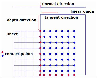
Figure 25.54 Sheet to linear guide contact
25.6.2.1. Modeling Options
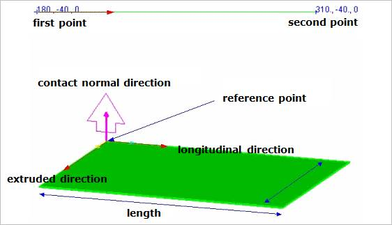
Figure 25.55 Linear Extrusion Guide
Point, Point
Point: Selects a point to define a start point of the linear guide.
Point: Selects a point to define an end point of the linear guide.
Point, Point, Depth
Point: Selects a point to define a start point of the linear guide.
Point: Selects a point to define an end point of the linear guide.
Depth: Defines a depth of the linear guide.
Point, Point, Direction, Depth
Point: Selects a point to define a start point of the linear guide.
Point: Selects a point to define an end point of the linear guide.
Direction: Defines a depth direction of the linear guide.
Depth: Defines a depth of the linear guide.
MultiPoint
MultiPoint: Selects some points.
GuideMotherBody, Point, Point
GuideMotherBody: Selects a body to define the parent body of the linear guide.
Point: Selects a point to define a start point of the linear guide.
Point: Selects a point to define an end point of the linear guide.
GuideMotherBody, Point, Point, Depth
GuideMotherBody: Selects a body to define the parent body of the linear guide.
Point: Selects a point to define a start point of the linear guide.
Point: Selects a point to define an end point of the linear guide.
Depth: Defines a depth of the linear guide.
GuideMotherBody, Point, Point, Direction, Depth
GuideMotherBody: Selects a body to define the parent body of the linear guide.
Point: Selects a point to define a start point of the linear guide.
Point: Selects a point to define an end point of the linear guide.
Direction: Defines a depth direction of the linear guide.
Depth: Defines a depth of the linear guide.
GuideMotherBody, MultiPoint
GuideMotherBody: Selects a body to define the parent body of the linear guide.
MultiPoint: Selects some points.
25.6.2.2. Properties
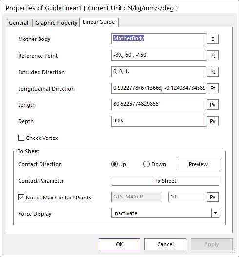
Figure 25.56 Guide Linear property page [Linear Guide page]
Mother Body: Defines the name of the guide body including the guide.
Reference Position: Defines the position of reference marker of the extruded line geometry.
Longitudinal Direction: Defines the x-axis of reference marker of the extruded line geometry.
Extruded Direction: Defines the z-axis of reference marker of the extruded line geometry.
Length: Defines the length of the extruded line geometry.
Depth: Defines the depth of the extruded line geometry.
Contact Direction: Shows the direction of the contact with the sheet on the guide.
Contact Parameter: Modifies the contact parameter between the guide and the sheet.
Check Vertex: When the size of a guide is smaller than that of a contacted shell element, the contact is not worked. In this case, if this option is on, the four vertexes of the guide are checked in the sheet-to-guide contact.
Contact Parameter: Allows the user to modify contact parameters by clicking To Sheet. In this dialog box, the user can modify the contact parameters of contact forces applied between the sheet and the guide. Refer to Contact Formulations for MTT3D.
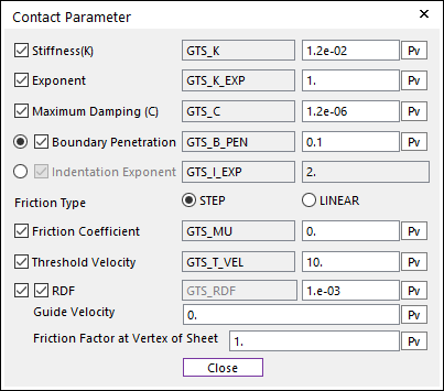
Figure 25.57 Contact Parameter dialog box
No. of Max Contact Points: Defines the number of max contact point for output. User can define this value from 1 to 5000. This value only affects Force Display and RPLT data about the contact points. The default value is 10.
Force Display: Graphically displays the all contact force vectors (the sum of the normal and tangential contact force) at each contact point up to the No. of Max Contact Point.