25.11. Specialized Outputs
RecurDyn/MTT3D automates to generate the relevant outputs for the sheet feeding system. Sometimes, the user wastes a valuable time and the extra cost for changing the outputs from a general purpose program into datasets needed to design or analyze the system. But, RecurDyn/MTT3D positively offers the outputs needed for analyzing the media transport system to the user. The below table summarizes the outputs for RecurDyn/MTT3D.
Group |
Plot Content |
Outputs |
Sheet |
Pos_ |
Position and Z-X-Z euler angles of the specified sheet bodies |
Vel_ |
Velocity of the specified sheet bodies. The translational Velocity is measured in the global reference frame. The angular velocity is measured in the reference frame of sheet body (or nodal). |
|
Acc_ |
Acceleration of the specified sheet bodies. The translational acceleration is measured in the global reference frame. The angular acceleration is measured in the reference frame of sheet body (or nodal). |
|
_Contact |
Contact forces generalized at a node. The force is measured in the reference frame of sheet body (or nodal). |
|
Impulse |
Impulse of contact forces (= |F|*dt) |
|
_Elastic |
Generalized elastic forces. This force is calculated from the element stiffness matrix and deformation of a node. The force is measured in the reference frame of sheet body (or nodal). |
|
_Nodal |
Generalized nodal forces at the specified node. If there is no nodal force on the node, the result is zero. The force is measured in the reference frame of sheet body (or nodal). |
|
_Ai r_Resistance |
Air Resistance Forces. If the Air Resistance Coefficient option is not checked, the result is zero. The force is measured in the reference frame of sheet body (or nodal). |
|
EX,EY,EZ ,EXY,EYZ,EZY |
Strain tensor. The tensor is measured in the global reference frame. For more information, refer to Post Process in FFlex. |
|
E1,E2,E3 |
Principal strain. For more information, refer to Post Process in FFlex. |
|
EINT |
Intensity strain. For more information, refer to Post Process in FFlex. |
|
EMISES |
Von-Mises strain. For more information, refer to Post Process in FFlex. |
|
SX,SY,SZ ,SXY,SYZ,SZY |
Stress tensor. The tensor is measured in the global reference frame. For more information, refer to Post Process in FFlex. |
|
S1,S2,S3 |
Principal stress. For more information, refer to Post Process in FFlex. |
|
SINT |
Intensity stress. For more information, refer to Post Process in FFlex. |
|
SMISES |
Von-Mises stress. For more information, refer to Post Process in FFlex. |
|
Fixed Roller |
MeanDPEN_SHT |
Mean value of the derivatives of a penetration with respect to the time of the contact normal direction at contact points between the roller and the sheet. The value is calculated as the following equation. \(\sum\nolimits_{i=1}^{n}{{{\delta }_{i}}}/n\) where, \(n\) is the number of contact points. |
MeanRvelT_SHT |
Mean value of the relative velocities in the contact tangent direction (parallel to the tangent direction of roller) at contact points between the roller and the sheet. The value is calculated as the following equation. \({{\sum\nolimits_{i=1}^{n}{\left( {{({{v}_{s}})}_{t}}-{{({{v}_{fr}})}_{t}} \right)}}_{i}}/n\) where, \(n\) is the number of contact points. |
|
MeanRvelD_SHT |
Mean value of the relative velocities in the contact tangent direction (parallel to the depth direction of roller) at contact points between the roller and the sheet. The value is calculated as the following equation. \({{\sum\nolimits_{i=1}^{n}{\left( {{({{v}_{s}})}_{d}}-{{({{v}_{fr}})}_{d}} \right)}}_{i}}/n\) where, \(n\) is the number of contact points. |
|
NormalF_SHT |
Summation of forces in the contact normal direction at the contact points with the sheet. |
|
FrictionFT_SHT |
Summation of friction forces in the contact tangent direction (parallel to the tangent direction of roller) at the contact points with the sheet. |
|
FrictionFD_SHT |
Summation of friction forces in the contact tangent direction (parallel to the depth direction of roller) at the contact points with the sheet. |
|
Contact_SHT |
Contact forces generalized at the center of roller. The force is measured in the global reference frame. |
|
Impulse_DT |
Impulse of the driving torque for a revolute joint (= |T|*dt) |
|
ContactPoints |
The contact points data are written sorted by the bigger normal force. Each contact point data are 15 values includes contact position vector, normal direction vector, friction direction vector, penetration depth, penetration velocity, tangential relative velocity, friction coefficient, normal force, and friction force. The number of outputs is defined as the No. of Max Contact Point on the Contact page of the properties dialog. |
|
MovableRoller |
MeanDPEN_SHT |
Mean value for the derivatives of a penetration with respect to the time of the contact normal direction at contact points between the roller and the sheet. The value is calculated as the following equation. \(\sum\nolimits_{i=1}^{n}{{{\delta }_{i}}}/n\) where, \(n\) is the number of contact points. |
MeanRvelT_SHT |
Mean value of the relative velocities in the contact tangent direction (parallel to the tangent direction of roller) at contact points between the roller and the sheet. The value is calculated as the following equation. \({{\sum\nolimits_{i=1}^{n}{\left( {{({{v}_{s}})}_{t}}-{{({{v}_{mr}})}_{t}} \right)}}_{i}}/n\) where, \(n\) is the number of contact points. |
|
MeanRvelD_SHT |
Mean value of the relative velocities in the contact tangent direction (parallel to the depth direction of roller) at contact points between the roller and the sheet. The value is calculated as the following equation. \({{\sum\nolimits_{i=1}^{n}{\left( {{({{v}_{s}})}_{d}}-{{({{v}_{mr}})}_{d}} \right)}}_{i}}/n\) where, \(n\) is the number of contact points. |
|
NormalF_SHT |
Summation of forces in the contact normal direction at the contact points with the sheet. |
|
FrictionFT_SHT |
Summation of friction forces in the contact tangent direction (parallel to the tangent direction of roller) at the contact points with the sheet. |
|
FrictionFD_SHT |
Summation of friction forces in the contact tangent direction (parallel to the depth direction of roller) at the contact points with the sheet. |
|
Contact_SHT |
Contact forces generalized at the center of roller. The force is measured in the global reference frame. |
|
MeanRevlT_FR |
Mean value of the relative velocities in the contact tangent direction (parallel to the tangent direction of roller) at contact points between the movable roller and the fixed roller. The value is calculated as the following equation. \({{\sum\nolimits_{i=1}^{n}{\left( {{({{v}_{mr}})}_{t}}-{{({{v}_{fr}})}_{t}} \right)}}_{i}}/n\) where, \(n\) is the number of contact points. |
|
NormalF_FR |
Summation of forces in the contact normal direction at the contact points with the fixed roller. |
|
FrictionFT_FR |
Summation of friction forces in a contact tangent direction (parallel to the tangent direction of roller) at the contact points with the fixed roller. |
|
Contact_FR |
Contact forces generalized at the center of roller. The force is measured in the global reference frame. |
|
MaxGap_NF |
Contact normal force for the maximum gap. |
|
SoftNip_NF |
Contact normal force for the soft nip. |
|
Impulse_DT |
Impulse of the driving torque for a revolute joint (= |T|*dt) |
|
ContactPoints |
The contact points data are written sorted by the bigger normal force. Each contact point data are 15 values includes contact position vector, normal direction vector, friction direction vector, penetration depth, penetration velocity, tangential relative velocity, friction coefficient, normal force, and friction force. The number of outputs is defined as the No. of Max Contact Point on the Contact page of the properties dialog. |
|
Linear Guide
Arc Guide
Circular Guide
Sheet to Surface Contact
Sheet to Sphere Contact
Sheet to Torus Contact
|
MeanDPEN_SHT |
Mean value for the derivatives of a penetration with respect to the time of the contact normal direction at contact points between guide and sheet. The value is calculated as the following equation. \(\sum\nolimits_{i=1}^{n}{{{\delta }_{i}}}/n\) where, \(n\) is the number of contact points. |
MeanRvelT_SHT |
Mean value of the relative velocities in the contact tangent direction (parallel to the tangent direction of roller) at contact points with the sheet. The value is calculated as the following equation. \({{\sum\nolimits_{i=1}^{n}{\left( {{({{v}_{s}})}_{t}}-{{({{v}_{g}})}_{t}}-{{v}_{gvel}} \right)}}_{i}}/n\) where, \(n\) is the number of contact points. vgvel is the Guide Velocity. |
|
M eanRvelD_SHT |
Mean value of the relative velocities in the contact tangent direction (parallel to the depth direction of guides) at contact points with the sheet. The value is calculated as the following equation. \({{\sum\nolimits_{i=1}^{n}{\left( {{({{v}_{s}})}_{d}}-{{({{v}_{g}})}_{d}} \right)}}_{i}}/n\) where, \(n\) is the number of contact points. |
|
NormalF_SHT |
A scalar value and summation of magnitudes of contact normal force at all contact points. \({{\sum\nolimits_{i=1}^{n}{\left( {{f}_{n}} \right)}}_{i}}\) |
|
FrictionFT_SHT |
A scalar value and summation of magnitudes to tangential direction of contact friction force at all contact points. \({{\sum\nolimits_{i=1}^{n}{\left( {{f}_{ft}} \right)}}_{i}}\) In the case of Sheet to Surface/Sphere/Torus contact, the tangent direction is specially defined for each contact case. Refer to the NOTE below this table. |
|
FrictionFD_SHT |
A scalar value and summation of magnitudes to depth direction of contact friction forces at all contact points. \({{\sum\nolimits_{i=1}^{n}{\left( {{f}_{fd}} \right)}}_{i}}\) In the case of Sheet to Surface/Sphere/Torus contact, the tangent direction is specially defined for each contact case. Refer to the NOTE below this table. |
|
Contact_SHT |
Contact forces between sheet and a guide or a rigid body. Reference frame of the force vector is the inertia marker of the ground body. In order to report, the summation of contact force is converted a force which is acting on the reference marker of the guide surface (Linear/Arc/Circular guide) or the CM marker of the rigid body (Sheet to surface/sphere/torus). |
|
ContactPoints |
The contact points data are written sorted by the bigger normal force. Each contact point data are 15 values includes contact position vector, normal direction vector, friction direction vector, penetration depth, penetration velocity, tangential relative velocity, friction coefficient, normal force, and friction force. The number of outputs is defined as the No. of Max Contact Point on the Contact page of the properties dialog. |
|
Sensor |
Speed Sensor |
Speed of the closest sheet in the specified direction of the sensor. |
Event Sensor |
When a head or trail of sheet passes to the sensor, the result is 1, or not 0. Also, the user can know the time when the sheet goes to the sensor. |
|
Distance Sensor |
Distance of the closest sheet in the specified direction of the sensor. |
|
Tension Sensor |
Stress of the closest sheet in the sensor. |
Definition for Reference Frame
Naming rule of plot data for the Sheet to Surface, Sheet to Sphere and Sheet to Torus contact is the same as guide contacts. A rigid body defined in the Sheet to Surface, Sheet to Sphere and Sheet to Torus contact has a general shape Therefore, tangential direction and depth direction cannot be easily defined in generally for the friction force FrictionFT_SHT (Tangentail direction) and FrictionFD_SHT (Depth direction). Therefore, in the MTT3D toolkit has a special assumption. The definitions of the tangential and depth direction is related the contact reference frame of the Sheet to Surface, Sheet to Sphere and Sheet to Torus contact. The x, y, and z axis is defined as tangential, normal, and depth direction respectively in contact reference frame. The following figure shows the contact reference frame.
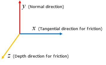
Figure 25.82 Definition of contact reference frame of the Sheet to (Surface/Sphere/Torus) contact
The NoramlF_SHT, FrictionFT_SHT and FrictionFD_SHT for the Sheet to Surface, Sheet to Sphere and Sheet to Torus contact are a summation value of scalar values. Therefore, these values cannot be used in order to retrieve a total contact force vector. Because, the contact reference frames are not the same at all contact points like following figure.
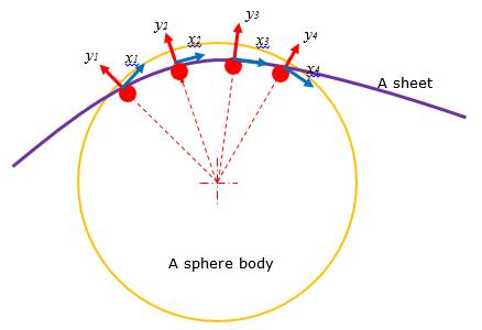
Figure 25.83 Example of Sheet to Sphere contact
Following three figures show how contact reference frame is defined in the Sheet to Surface, Sheet to Sphere and Sheet to Torus contact case.
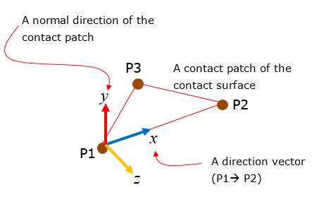
Figure 25.84 Definition of contact reference frame for Sheet to Surface contact
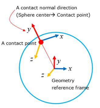
Figure 25.85 Definition of contact reference frame for Sheet to Sphere contact
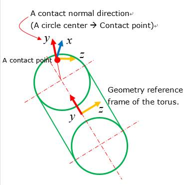
Figure 25.86 Definition of contact reference frame for Sheet to Torus contact