12.1.1. Step to Create Multi-mesh
Step to use Auto Flex Merge
Beam type
Using Shell type as source body and Solid type as target body
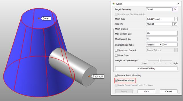
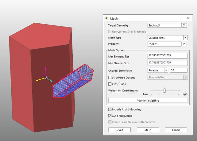
In Auto Mesh, mesh the source body with the Auto Flex Merge option checked.
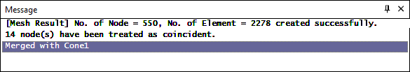
Check the following messages are displayed in the message window.
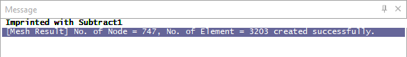
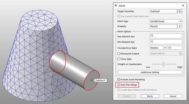
In Auto Mesh, mesh the target body with the Auto Flex Merge option checked.
Check the following messages are displayed in the message window.
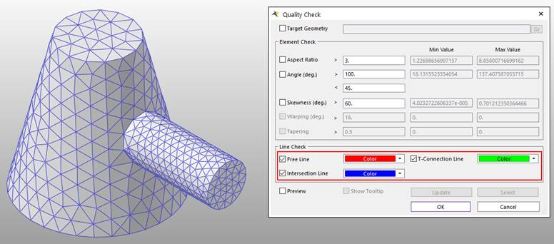
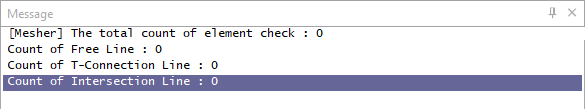
Check if Flex Merge was successful with Line Check of Quality Check.
Step to manually Flex Merge
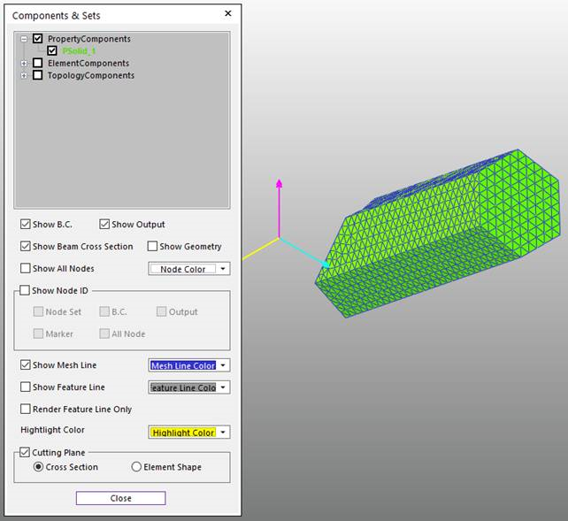
Mesh the Source Body.
Check off the Show Geometry in FFlex Display to see the result clearly.
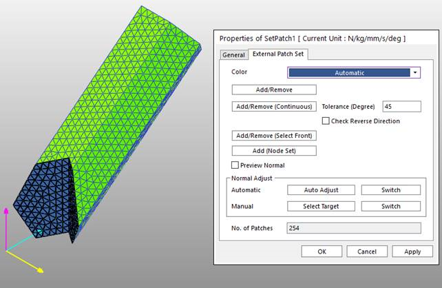
Create PatchSet to the surface where two bodies meet in the Meshed Source Body.
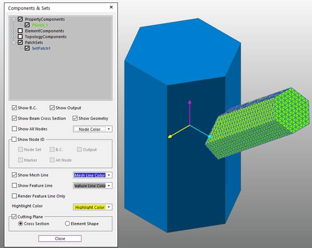
- Check on the Show Geometry in FFlex Display to see the
Target Geometry again.
Create Edge to the Target Geometry using Imprint Line in the Geometry Tab or Imprint Edge in the Mesher Tab.
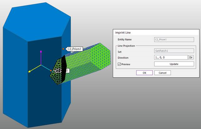
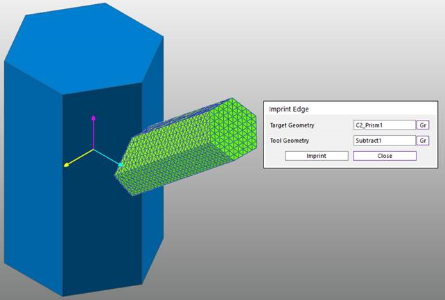
Note
Imprint Line uses outermost line of Patch Set or Line Set and project it on the Surface of the entity. Imprint Edge uses geometry of meshed body and perform intersection to create edge.
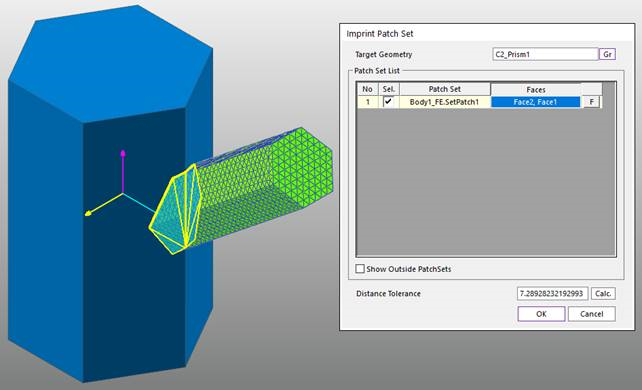
Use Imprint Patch Set to the Target Geometry.
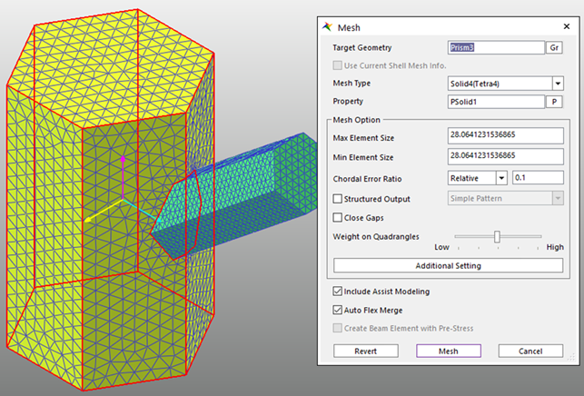
Mesh the Target Geometry.
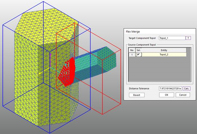
Use Flex Merge to merge the Source Geometry and Target Geometry.