29.2.10. Timing Pulley
The timing pulley is a geometric entity created the pulley with an arbitrary tooth profile or the shape defined ISO 5294.
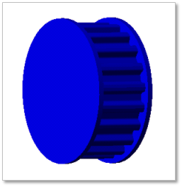
Figure 29.48 Timing pulley geometric entity
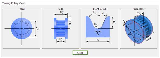
Figure 29.49 Timing pulley dimension information
A |
Angle |
Hr |
Tooth Height |
Bg |
Tooth Length |
R1 |
Tooth Root Radius |
R2 |
Tooth Tip Radius |
Do |
Outside Diameter |
H |
Flange Height |
Wp |
Pulley Width |
Wf |
Flange Width |
29.2.10.1. Modeling Options
The user can create a timing pulley as follows.
Point, WithDialog
Point: Selects a point to define the center of the timing pulley.
WithDialog: Modifies the property for the timing pulley. The timing pulley is created with clicking OK.
29.2.10.2. Properties
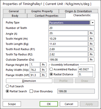
Figure 29.50 Timing Pulley property page [Characteristic page]
The Timing Pulley property page is shown in Figure 29.50. The parameters are explained below.
Pulley Type: 2 types are supported in RecurDyn/Belt.
Number of Teeth: Enters the number of teeth.
Flange Height (H): Enters the flange height of timing pulley.
Pulley Width (Wp): Enters the width of timing pulley.
Flange Width (Wf): Enters the width of timing pulley.
Assembly Information
Assembled Radius: Enters the radius with that the timing belts wrap the timing pulley.
Radial Distance: Enters the radial distance between belt and pulley when the timing belts wrap the timing pulley.
Full Search: If this is checked, all belt bodies are searched for contact with the timing pulley.
Partial Search: If this is checked, belt bodies within the given bounds are searched for the contact with the timing pulley.
User Boundary: Enters the range of boundary.
29.2.10.2.1. Pulley Type
General
Uses the needed timing pulley shape with an arbitrary tooth profile.
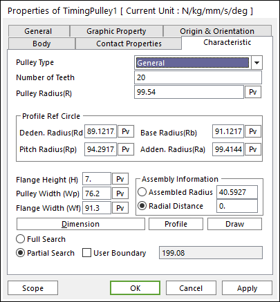
Figure 29.51 Timing Pulley property page [General type]
Pulley Radius(R): Enters the radius of pulley.
Dedendum Radius(Rd): Enters the dedendum circle radius of tooth profile.
Base Radius(Rb): Enters the base circle radius of tooth profile.
Pitch Radius(Rp): Enters the pitch circle radius of tooth profile.
Addendum Radius(Ra): Enters the addendum circle radius of tooth profile.
Profile
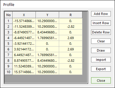
Figure 29.52 Profile dialog box
X,Y,R: Points and radius.
Add Row: Adds a row to the end of the table.
Insert Row: Inserts a row where the cursor is and move the current and later rows down.
Delete Row: Deletes the row where the cursor is and move the later rows up.
Clear: Deletes all rows in the table.
Draw: All data must be defined with respect to the link marker. You can move points graphically by using the mouse directly.
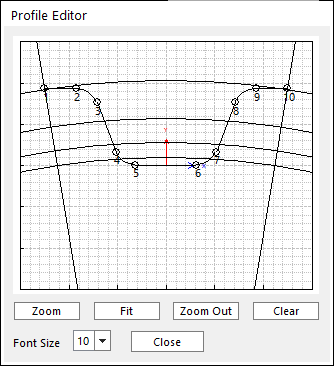
Figure 29.53 Profile Editor dialog box
Import: Imports the X, Y, and R data pairs from a CSV file or a MAT file or a text file. In the case of the text file, the usage of the comma, the tab, and the space can be the delimiter between the three columns in the file. And when using the Excel file, the user can select the Tab-delimited text file output option or the CSV (Comma-Separated Values) file output option to save the Excel file which can be imported.
Export: Exports the X, Y, and R data pairs to a CSV file or a MAT file or a text file.
Parameter
Uses the needed timing pulley shape with an arbitrary tooth profile.
Figure 29.54 Timing Pulley property page [Parameters type]
In order to understand the geometry, refer to Dimension Information.
Angle (A): Enters the angle of timing pulley. [Degree]
Tooth Height (Hr): Enters the tooth height of timing pulley.
Tooth Length (Bg): Enters the tooth length of timing pulley.
Tooth Root Radius (R1): Enters the tooth root radius of timing pulley.
Tooth Tip Radius (R2): Enters the tooth tip radius of timing pulley.
Outside Diameter (Do): Enters the outside diameter of timing pulley.