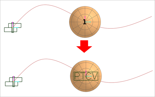
A ptcv joint constraints one point of a body to lie on a curve defined on the other body. The curve must have been defined prior to creating the PTCV joint. This joint has four degrees of freedom.
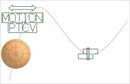
In the Figure 6.226, the ellipsoid body is free to roll and slide on the fixed curve. The curve can be planar or spatial or open or closed. The ellipsoid body cannot lift off the curve; it must always lie on the curve. A point-curve constraint removes two translational degrees of freedom from the model.
Point: Selects a point near the curve. RecurDyn automatically finds the closest curve to the point and makes an initial guess of the contact position.
Curve, Point
Curve: Selects a curve.
Point: Selects a point near the curve. RecurDyn automatically finds the closest curve to the point and makes an initial guess of the contact position.
Curve, Body, Point
Curve: Selects a curve.
Body: Selects an action body of the ptcv joint.
Point: Selects a point near the curve. RecurDyn automatically finds the closest curve to the point and makes an initial guess of the contact position.
MulitCurve, Body, Body, Point
MultiCurve: Selects some curves. To finish selecting curves, click the empty space with the right mouse button and choose Finish Operation on right-click menu. After selecting, the new curve is created as connecting selected curves.
Body: Selects a base body of the ptcv joint.
Body: Selects an action body of the ptcv joint.
Point: Selects a point near the curve. RecurDyn automatically finds the closest curve to the point and makes an initial guess of the contact position.
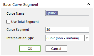
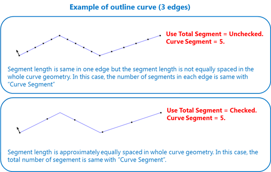
Use Total Segment: If this option is selected, the user can make approximately equally spaced contact segments on the curve by using the Curve Segment information although there are multiple edges in a curve geometry. This option is available for a rigid body.
Figure 6.229 The example of the Use Total Segment option in the case of Curve Segment = 5.
Curve Segment: If the Use Total Segment option is not checked, Curve Segment means the number of segments in an edge or the number of segments between the user-specified control points. If the Use Total Segment option is checked, Curve Segment means the number of segments in the whole connected edge.
If the user increases this number, the number of points is increased and the approximated contact curve is close to the real curve. If the curve is a Line Set of a flexible body, this value just shows the number of lines including the Line Set. The maximum number of total curve segments is 500,000.
Interpolation Type: Selects an interpolation type of the curve to as Curve (non-uniform), Poly5 (non-uniform)Curve (uniform), Poly5 (uniform).
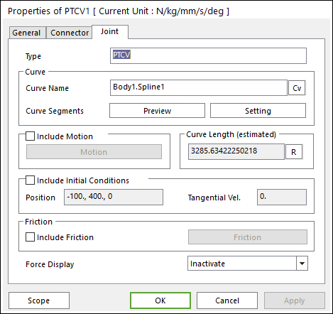
Include Motion: Defines the motion of the ptcv joint. Refer to Motion.
Include Initial Conditions: Define the initial conditions of the ptcv joint.
Position: Changes the initial point position on the curve.
Tangential Velocity: Defines the tangential velocity along the curve.
Friction
Include Friction: If this option is checked, the friction force can be defined for the ptcv joint. Only the Sliding type is supported. For more information, click
here.
Force Display: Displays the resultant force vector graphically on Working Window.
Interpolation Type selects an interpolation type of the curve to as Cubic (non-uniform), Poly5 (non-uniform), Cubic (uniform), and Poly5 (uniform).
Cubic(non-uniform)
Cubic spline method. This option is used when the lengths of segments are the same or different. (Recommended)
Poly5(non-uniform)
5th polynomial spline method. This option is used when the lengths of segments are the same or different.
Cubic(uniform)
Cubic spline method. This option is for the prior solution. It is recommended when the lengths of segments are the same.
Poly5(uniform)
5th polynomial spline method. This option is for the prior solution. It is recommended when the lengths of segments are the same.
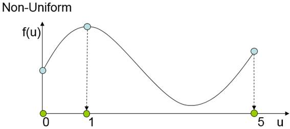
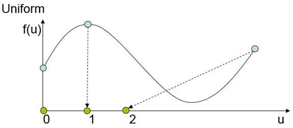
Non-uniform and Uniform are the parameterization method of a curve.
The parameterized value is determined by the length of the curve segment in the Non-uniform. But the parameterized value of regular intervals is determined regardless of the length of the curve segment in the Non-uniform.
If the lengths of curve segments are the same, the results of Non-uniform and Uniform are the same. But, if the lengths of curve segments are different, the result of Non-uniform is better than the result of Uniform.
Open curve
When the curve is the open loop, the quadric differential values for the initial point and final point are the same in Curve (uniform).
When the curve is the open loop, the quadric and cubic, and quartic differential values for the initial point and final point are the same in Poly5 (uniform).
When the curve is the open loop, the quadric values for the initial point and final point are zero in Curve (non-uniform).
When the curve is the open loop, the quadric and cubic, and quartic differential values for the initial point and final point are zero in Poly5(non-uniform).
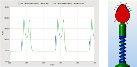
Comparison for the simulation result of cubic(non-uniform) with cubic(uniform)
Non-uniform
The curve is composed of the non-uniform segments as shown in the above figure and the model is simulated for cubic (non-uniform) and cubic (uniform) cases. The normal contact forces are shown in the above plot. The blue line is the result of cubic (uniform) and the green line is the result of cubic (non-uniform). In the case of the cubic (uniform), there is a noise at which the length of the segment is changed.
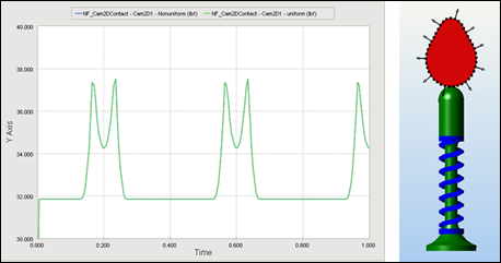
Uniform
The curve is composed of uniform segments as shown in the above figure and the model is simulated for cubic (non-uniform) and cubic (uniform) cases. The normal contact forces are shown in the above plot. The blue line is the result of cubic (uniform) and the green line is the result of cubic (non-uniform). The result of cubic (uniform) is the same as that of cubic (non-uniform).
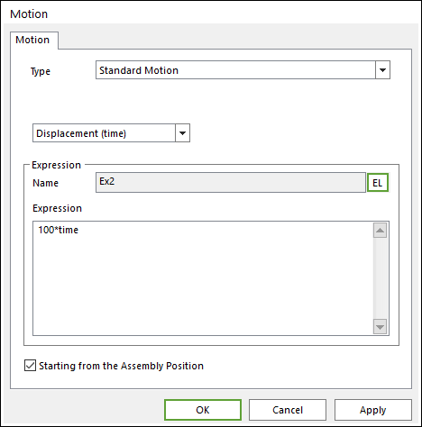
A motion for the ptcv joint is the same as other joints. In the case of the ptcv joint, only the displacement and velocity type of the motion is supported, and the Starting from the Assembly Position option is added.
Refer to Motion.
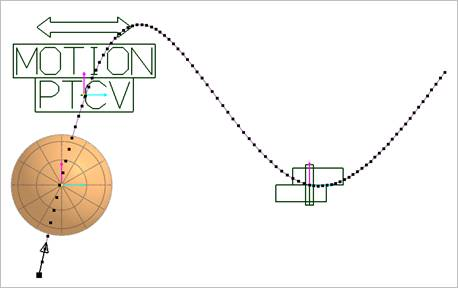
When the user wants to identify the start point of the curve, the
Preview for Curve Segments can be used. The first point is displayed as a bigger point and the direction of the curve is displayed by an arrow.