11.1.2.1. Method RIGID to FFLEX
If a Rigid body is selected as a source body for G-Manager, FFlex and RFlex body can be converted. When the target body is FFlex body, two methods are supported to convert FFlex body.
11.1.2.1.1. (1) FFlex : Mesh
When the target body is FFlex body, if the user wants to mesh a rigid body using RecurDyn/Mesher, Mesh type can be used. In this case, only enters to Mesh mode.
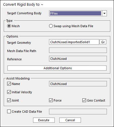
Figure 11.6 Mesh Type
Target Converting Body: Selects a target body type. In this case, please select FFlex.
Type: Selects a method how to change from Rigid to FFlex. In this case, please select Mesh.
Options
Target Geometry: Selects a target geometry to mesh. This cannot be changed in Mesh mode.
Additional Options
Assist Modeling: some items can be maintained after converting process.
Name: Maintains the name of source body.
Initial Velocity: Maintains the initial velocity of source body.
Joint: Maintains Joint entities related to the source body.
Force: Maintains Force entities related to the source body.
Geo Contact: Maintains Geo Contact entity related to the source body. Other Contact entities are not supported.
Create CAD Data File: If this option is checked, the CAD file for the original rigid body is created in the defined directory when converting to other types.
11.1.2.1.2. (2) FFlex : Swap using Mesh Data File
When the target body is FFlex body, if the user wants to swap with a mesh data file, Swap using Mesh Data File type can be used.
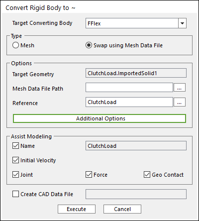
Figure 11.8 Swap using Mesh Data File Type
Target Converting Body: Selects a target body type. In this case, please select FFlex.
Type: Selects a method how to change from Rigid to FFlex. In this case, please select Swap using Mesh Data File.
Options
Mesh Data File Path: Defines a path of the file that is used to swap.
Reference: Defines a reference frame that is used to swap.
Additional Options
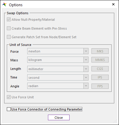
Swap Options: When Rigid body is converted to FFlex body, some options are needed. For more information about this dialog, please refer to Import dialog box. in FFlex.
Use Force Connector of Connecting Parameter: Determines how to connect between the dummy body and nodes. The default is unchecked. For more information, click here.
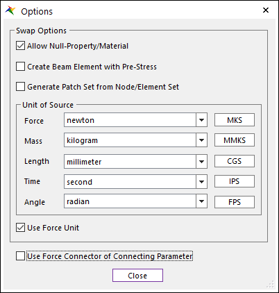
Figure 11.9 Options dialog box
Assist Modeling: some items can be maintained after converting process.
Name: Maintains the name of source body.
Initial Velocity: Maintains the initial velocity of source body.
Joint: Maintains Joint entities related to the source body.
Force: Maintains Force entities related to the source body.
Geo Contact: Maintains Geo Contact entity related to the source body. Other Contact entities are not supported.
In the case of Geo Surface Contact, a Patch Set is created for the whole surface of the base or action geometry.
In the case of Geo Curve Contact, a Line Set is created for the first edge of the base or action geometry.
Create CAD Data File: If this option is checked, the CAD file for the original rigid body is created in the defined directory when converting to other types.