6.4.2.5. UV Sphere
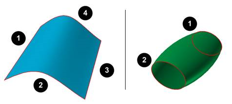
A UV Sphere Contact calculates contact forces between primitive sphere and UV surface. GUI provides node and rectangular 4-node patch which is discretized with UV data. Rectangular patches are in uniform patch size and well-arranged. Target UV surface is a geometry which can be UV-parametrized. An opened UV surface has 4 edges and a closed UV surface has 2 edges. If smooth face contact option is activated, bi-cubic Hermite surface is generated and it provides smooth contact between surface and primitive sphere.
6.4.2.5.1. Modeling Options
Surface(4-sided Surface, UV Surface), Sphere
Surface(4-sided Surface, UV Surface): Selects a UV surface.
Sphere: Selects a sphere to define an action sphere.
Surface(4-sided Surface, UV Surface), MultiSphere
Surface(4-sided Surface, UV Surface): Selects a UV surface.
MultiSphere: Selects some spheres to define action spheres.
Surface(4-sided Surface, UV Surface), Sphere, Surface(4-sided Surface, UV Surface), Sphere
Surface(4-sided Surface, UV Surface): Selects a UV surface.
Sphere: Selects some spheres to define action spheres.
Surface(4-sided Surface, UV Surface): Selects a UV surface.
Sphere: Selects some spheres to define action spheres.
MultiSurface(4-sided Surface, UV Surface), MultiSphere
MultiSurface(4-sided Surface, UV Surface): Selects UV surfaces.
MultiSphere: Selects some spheres to define action spheres.
Note
The user must use the surface which have 2 or 4 edges when creating the UV Sphere contact.
6.4.2.5.2. Properties
In the case of UV Sphere contact, the property page is same to Geo Surface contact.For more information, click here.
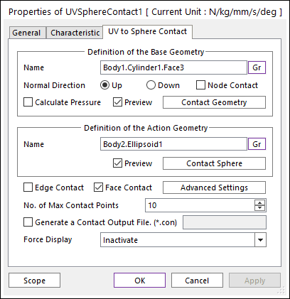
Figure 6.337 Properties of UVSph dialog box
Contact Geometry: Accesses the Surface Patch dialog box as shown in the below figure.
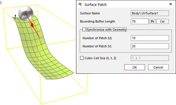
Figure 6.338 Surface Patch dialog box
Surface Name: This shows the name of the selected base contact geometry.
Bounding Buffer Length: This value is used when the contact pre-search is performed with base and action bounding box. The bounding buffer length defines the offset length of bounding box compared to the real bounding box as shown in the below figure. This value is automatically calculated but can be modified by the user. Additionally, if you click Cal., this value is updated with the recommended default value.
Synchronize with Geometry: If the surface is a UV surface, this option is enabled. If the option is checked, the U and V value of the UV surface geometry are used to the contact surface patch option. If it’s no checked, the numbers of UV patch in this dialog box are used to the contact surface patch option.
Number of Patch (U): This value defines the number of quad patch in U direction in UV surface.
Number of Patch (V): This value defines the number of quad patch in V direction in UV surface.
Cubic Cell Size: Shows the number of cubic cells dividing a contact bounding box in each direction. This value is automatically calculated but can be modified by the user.