40.2.2. Properties
The user can modify the property using the MMS Type B property page.
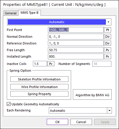
Figure 40.15 MMS Type B property page
First Point: The spring starting location defines the spring bottom position. This point with the Normal Direction is used to define the spring longitudinal axis and thus the global position and orientation of the spring within RecurDyn model. The automatic sequential numbering of the single segment bodies, joints and axial forces starts counting from this point. Thus, used as the starting point of the spring shell graphics. The first point is not the direct location of the bottom segment body location.
Normal Direction: The direction vector in global coordinates defines the longitudinal spring axis orientation. Refer to below Figure 40.16
Reference Direction: The direction vector in global coordinates which only defines the starting location of the spring shell graphics and thus dose not influence then spring characteristics. The reference direction is projected onto the spring bottom plane, which is perpendicular to the normal direction. Refer to below Figure 40.16.
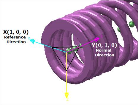
Figure 40.16 Normal / Reference Direction
Free Length: The undeformed length of the spring. This value is used only for the spring graphics. It does not affect the damping and stiffness splines nor the axial segment body locations, thus has no direct influence to spring characteristics. The reason is that the spring of helical shape is governed by the skeleton and wire profile information. In case that free length is smaller than the highest ‘Height’ - value in the skeleton profile plus vertical wire radius the related geometry of the spring is cut (flattened). For further information, please refer to Note 1 of this section.
Installed length: The length of spring in the deformed (installed) position. This value is used only for the spring graphics and for calculating the axial segment positions resulting from a possible pre-load situation, which occurs if Installed Length differs from Free Length. The calculated segment positions due to spring pre-loading include possible coil clash situations caused by this initial spring deformation. Like Free Length it does not affect the damping and stiffness splines, thus has no direct influence on the general spring characteristic. For further information please refer to Note 2 of this section.
Inactive Coils: The number of coils which do not contribute to the mass distribution of internal segment bodies. The number of Inactive Coils does not influence the spring/damper splines. Because they are calculated from the actual skeleton and wire profile information. For further information about the segment mass distribution, please refer to Note 2 of this section.
Number of segments: The number of connecting force elements. RecurDyn generates Number of Segments +1 body, which are connected by Number of Segments connection forces. Note that the Number of Segments cannot be changed with Modify option of spring because this value is related to the spring model topology.
Update Geometry Automatically: If this option is unchecked, the position and orientation of the geometry constituting the group are not updated depending on variables in the property page. So, after executing Extract function, this option is unchecked.
Each Rendering: The selected mode can be displayed in Each Render mode.