2.2.6. View Control Toolbar
This supports functions to control the view of the Working Window.
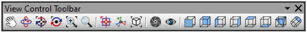
Figure 2.51 View Control Toolbar
View Operation
Translate: Translate a view of the Working Window. Shortcut is the T key.
Rotate: Rotate a view of the Working Window around a view center of window. Shortcut is the R key.
Rotate with Predefined Point: Select the center of rotation. If the user selects a point with this function, a view of the Working Window rotate around that point. Press once more to reset.
Rotate with Point: Rotate a view of the Working Window around a point selected by user. Shortcut is the Y key.
Select Zoom: Zoom in the selected area. Shortcut is the S key.
Zoom: Zoom in / out around a point of mouse. Shortcut is the Z key.
View Center: Set the view center of window. Shortcut is the C key.
View Snap: Rotate entities to the Plan view or Isometric view of the nearest direction from the current view. Shortcut is the G key.
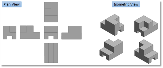
Figure 2.52 Plan view & Isometric view
Fit: Optimize the screen view. If an entity is selected, the screen focuses it. If not, the screen fits the view with all entities. Shortcut is the F key.
View Preset: Preset the view of window. Shortcut is the Ctrl + Shift + G keys.
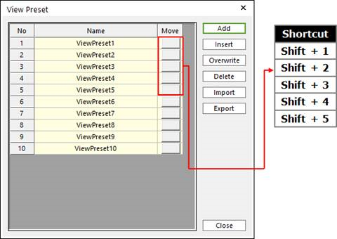
Figure 2.53 View Preset dialog box
No: Shows the number of view.
Name: Specifies the name of view.
Move: Move the saved view. Shortcut is the Shift + 1, 2, 3, 4, 5 keys. (Only No.1-5 of the list is defined.)
Add: Adds the row and save the current view.
Insert: Inserts the row and save the current view.
Overwrite: Overwrites the current view.
Delete: Deletes the row.
Import: Imports list of View Presets from the *.xml file.
Export: Exports list of View Presets to the *.xml file.
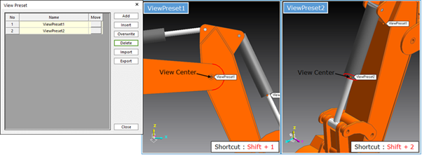
Figure 2.54 View Preset example
Custom View
The user can customize the view pointing.
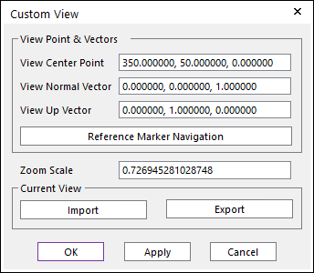
Figure 2.55 Custom View dialog box
View Point & Vectors
View Center Point: Defines the view center point.
View Normal Vector: Defines the view normal vector.
View Up Vector: Defines the view up vector.
Reference Marker Navigation: Navigates the reference marker.
Zoom Scale: Defines the zoom scale.
Current View
Import: Imports the Custom View Data File (*.xml).
Export: Exports the Custom View Data File (*.xml).
View Change
View at Front: Change the view to the front of a model.
View at Back: Change the view to the back of a model.
View at Left: Change the view to the left of a model.
View at Right:Change the view to the right of a model.
View at Top:Change the view to the top of a model.
View at Bottom: Change the view to the bottom of a model.
Isometric View: Change the view of a model using Isometric coordinates.
View at Plane: Change the view to the plane selected by user.
Step to Use View Preset
The user frequently modifies some parts of a model. In this case, the user always performed the Rotate function and the Translate function to see the desired part with inconvenience. But the View Preset function reduces the inconvenience by saving the view status to frequently modified parts in advance. The below example model of Figure 2.56 assumes that Part1, Part2, and Part3 are frequently modified and shows the method to use the View Preset function.
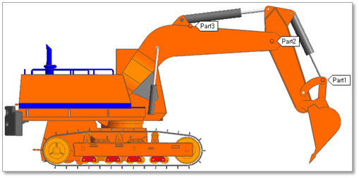
Figure 2.56 View Preset example model
Zoom in the surroundings of Part1 and then, perform the View Center function for setting Part1 to ViewPreset. The user can perform the View Center function by the C Key. (The user does not need to define View Center. But, if the user wants to correctly rotate Part 1, defining View Center is recommended.)
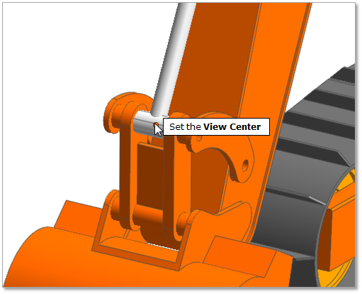
Figure 2.57 Set the view center of Part1
Set the desired view status by the Rotate function and the Zoom function. (The user notes to move the defined center of view if the Translate function is used.)
Open the View Preset dialog box. Shortcut is the Ctrl + Shift + G keys.
Click Add to save the view status of the Working Window. Change the name of saved ViewPreset1 to Part1.
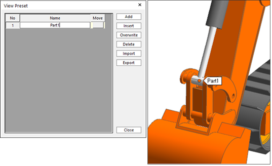
Figure 2.58 View Preset dialog box [Add and change the name]
Define ViewPrest of Part2 and ViewPrest of Part3 as shown in Figure 2.59.
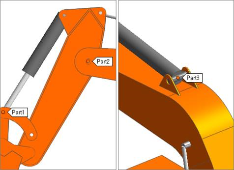
Figure 2.59 Set the View Preset of Part2 and Part3
Check whether to correctly save the VewPresets by clicking the Move buttons of each column in the View Preset dialog box.
Close the View Preset dialog box and then, use ViewPresets by pressing Shift+1, Shift+2, and Shift+3 when performing the modeling.