30.3.1. Modeling Options
Step to create an open loop chain system
Set up working plane to assembled plane to prevent assembly line from go through working plane. Click Assembly icon of the Assembly group in the Chain tab and select a point or a set of bodies with which the chain makes contacts.
Click the points from A to C to assemble the chain system and then click right button to choose Finish Operation on right-click menu. (Whenever a user moves the mouse, the underling body is highlighted, and users see the solid line connecting the previously selected body and the highlighted body. After making an open loop chain system, click the right button of mouse and choose Finish Operation on right-click menu. Then, the following dialog box for the chain links pops up.)
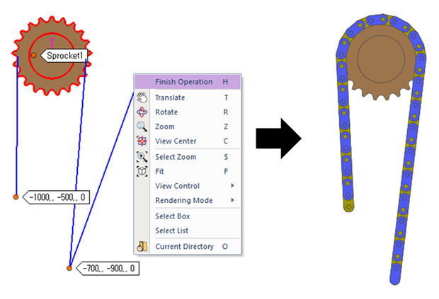
Figure 30.77 Chain assembly
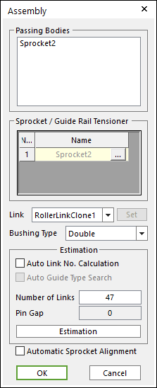
Figure 30.78 Assembly dialog box
Enter the number of links and click Estimation. A user can compute approximately pre-tension between chain links from an estimated pin gap.
Click OK, then the Chain assembly is completed.
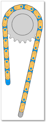
Figure 30.79 Chain Assembly complete
Step to create a closed loop chain system
Click Assembly icon of the Assembly group in the Chain tab and select a set of bodies with which the chain makes contacts.
Click the points from A to D to assemble the chain system. (Whenever a user moves the mouse, the underling body is highlighted and a user sees the solid line connecting the previously selected body and the highlighted body. After making a closed chain, the following dialog box for chain links pops up. )
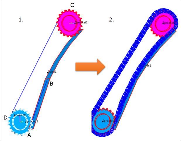
Figure 30.80 Chain assembly
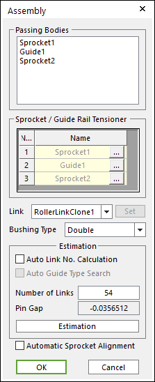
Figure 30.81 Assembly dialog box
Enter the number of links and click Estimation. A user can compute approximately pre-tension between chain links from an estimated pin gap.
Click OK, then the Chain assembly is completed.
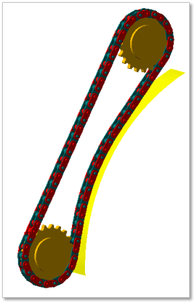
Figure 30.82 Chain Assembly complete
30.3.1.1. Assembly dialog box
During assembly, a below dialog box is shown.
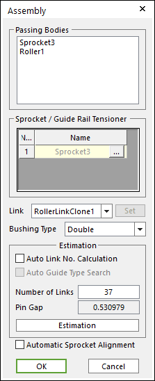
Figure 30.83 Assembly dialog box
Passing Bodies: Shows the list of assembled bodies.
Sprocket/Guide Rail Tensioner: Modifies the assembly information about Sprocket or Guide Rail Tensioner.
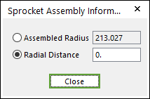
Figure 30.84 Sprocket Assembly Information dialog box
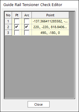
Figure 30.85 Guide Rail Tensioner Check Editor dialog box
Link: Selects a clone link. If the user clicks Set, the user can customize the generated link set.
Set: The user can use link sets wanted among the defined link sets. To use this function, the user must define link sets when creating clone of a link. For more information, click here.
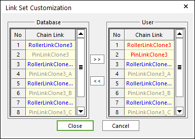
Figure 30.86 Link Set Customization dialog box
Link Set Customization
The user cannot move the first link and can compose user’s link by the database’s link.
The composed link set is marked in the RMD file.
Bushing Type: Selects a busing type. Refer to Bushing Force.
Estimation: The user can estimate the assembled links.
Auto Link No. Calculation: If the user clicks Estimation with the checked this option, the number of links is set automatically.
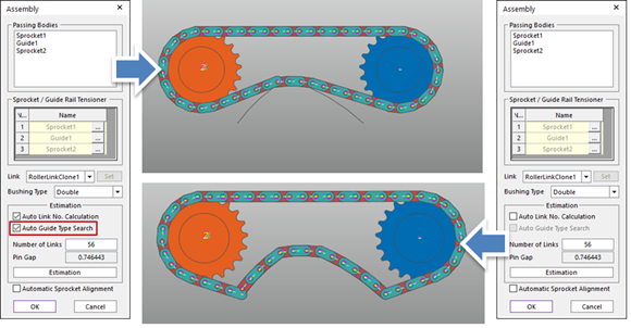
Auto Guide Types Search: If the user wants to maintain the Assembly Point of the Guide defined in Guide Rail Tensioner Check Editor dialog box of Sprocket/Guide Rail Tensioner function of the Assembly dialog box, this function can be used. If this function is on, always make an assembly with the initial assembly point automatically.
Number of Links: Modifies the number of links.
Pin Gap: Shows a value of pin gap.
Automatic Sprocket Alignment: If this option is checked, the sprockets are rotated to match the position of the links.
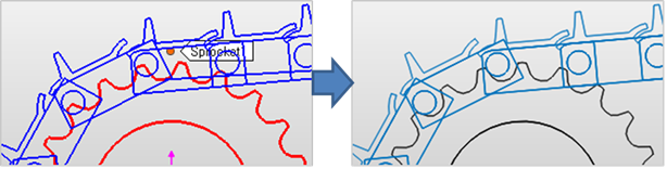
Figure 30.87 After using Automatic Sprocket Alignment option
Note
If there are interference between a sprocket and a link after finishing assembly with this option, the alignment is failed.
Tip