24.5.1. Flexible Fixed Roller
The flexible fixed roller uses a FFlex body consisting of a shell4 and FDR elements and is linked to ground and a revolute joint.
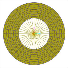
Figure 24.54 Flexible fixed roller
24.5.1.1. Modeling Options
The user can create the flexible fixed roller group as follows.
Point, Radius, WithDialog
Point: Selects a point to define the center of the flexible fixed roller group.
Radius: Defines a radius of the flexible fixed roller group.
WithDialog: Modifies the property for the flexible fixed roller group. The flexible fixed roller group is created with clicking OK.
24.5.1.2. Properties
The properties dialog box of the Flexible Fixed Roller has five tabs.
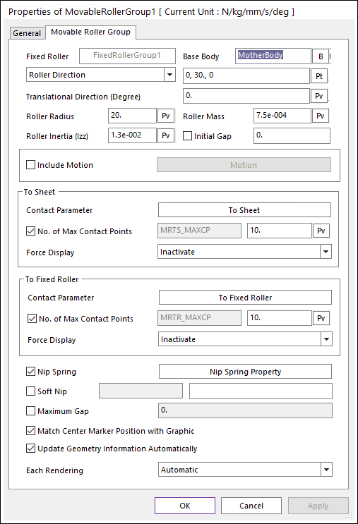
Figure 24.55 Flexible Fixed Roller Group property page [Flexible Fixed Roller Group page]
Base Body: Defines the base body of revolute joint.
Roller Center Point: Defines the center point of flexible fixed roller body.
Color: Defines the color of Shell4 element.
Depth: Defines the thickness of Shell4 element.
FDR Radius: Defines the radius of inner circle.
Roller Radius: Defines the radius of outer roller.
No. of Nodes at Circumference: Sets the number of nodes in the circumferential direction. This data cannot be changed after creation.
No. of Nodes at Radial: Sets the number of nodes in the radial direction. This data cannot be changed after creation.
Material Properties: Sets the user can change the material properties. If the user wants to check the detail information, refer to Flexible Information.
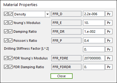
Figure 24.56 Material Properties dialog box for the flexible fixed roller
Include Motion: Defines the angular motion of the flexible fixed roller. The user can define the roller displacement, velocity and acceleration by using Expression. Refer to Motion.
Contact Parameter: Allows the user to modify contact parameters by clicking To Sheet. In this dialog box, the user can modify the contact parameters of contact forces applied between the sheet and the flexible fixed roller. Refer to Contact formulas for MTT2D.
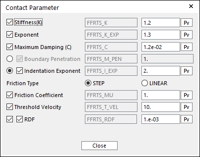
Figure 24.57 Contact Parameter dialog box
Match Center Marker Position with Graphic: If this is checked, the position of center marker of flexible fixed roller body is always matched with the center of roller geometry.
24.5.1.2.1. Output
The user can define output nodes. If the user sets output nodes, RecurDyn/Solver provides “position, velocity, acceleration, stress, strain, contact force and elastic force” in RPLT file.
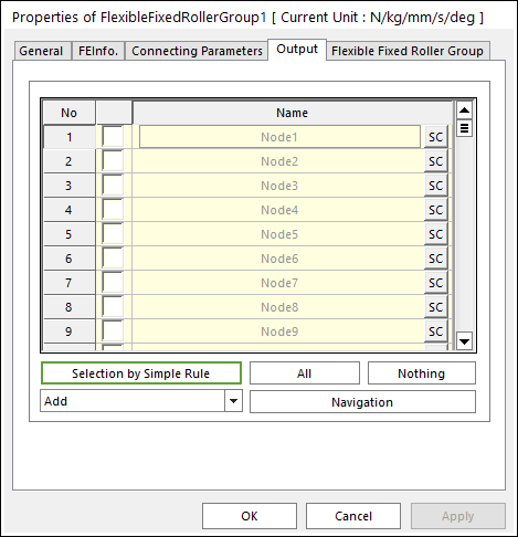
Figure 24.58 Flexible Fixed Roller Group property page [Output page]
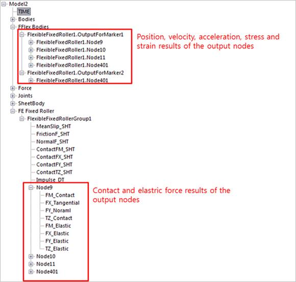
Figure 24.59 RPLT result using the output function of a flexible fixed roller