31.1.6. Scissors Gear
For most gears, backlash is provided for smooth engagement between two gears and rattling is generated by collision of the teeth due to this backlash while the gears rotate.
Scissors gears have been used to reduce the rattling. The scissors gear is applied to a driving gear or a driven gear and one gear is connected with the other gear by a scissors spring. Accordingly, when the teeth of a counterpart gear are engaged with the scissors gear, the teeth of the scissor gear are engaged with the teeth of the counterpart gear like scissors, such that backlash is removed and operational noise of the gears is reduced.
A scissors gear is composed of a set of two gear bodies. One gear body is connected to the other gear body by a Revolute joint and a Rotational spring.
Gear geometries are created from the parameters of ISO standards. The tooth profile is represented to multiple arcs. The sprocket tooth geometry data is:
Created from a predefined data file.
Edited from a predefined data file.
Exported from a predefined data file.
Imported from a predefined data file.
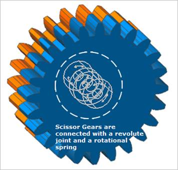
Figure 31.31 Scissors Gear
31.1.6.1. Properties
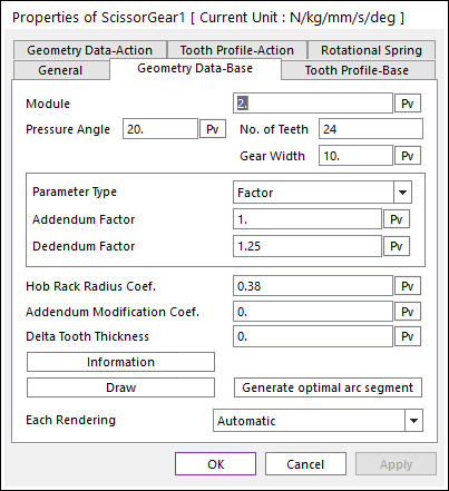
Figure 31.32 Scissor Gear property page [Geometry Data-Base page]
The Scissor Gear property page is shown in Figure 31.32. The parameters are explained below. In order to understand the geometry, refer to Geometric Entities.
Module: Enters the module of the gear.
Pressure Angle: Enters the pressure angle of the gear.
Number of Teeth: Enters the number of teeth. The maximum number of teeth of gear is 400.
Gear Width: Enters the width of the gear.
Parameter Type: two methods are supported to define the Addendum and Dedendum.
Factor: Defines the addendum and dedendum as factors. For more information, click here.
Addendum Factor: Enters the factor to define the addendum.
Dedendum Factor: Enters the factor to define the dedendum.
Addendum Radius & Whole Depth: Defines the addendum and dedendum as addendum radius and whole depth. For more information, click here.
Addendum Radius: Enters the addendum radius for the gear.
Whole Depth: Enters the whole depth as summation for the addendum and dedendum.
Hob Rack Radius Coef.: Enters the coefficient to define the hob rack radius. The default value is 0.38 (ISO 53, JIS Standard) and this should be equal or larger than 0. For more information, click here.
Note
In order to apply these values, The number of Under-Cut Arc should be defined in Tooth Profile page. For more information, click here.
Addendum Modification Coef.: Enters the coefficient to define the addendum.
Delta Tooth Thickness: Enters the delta value to define the tooth thickness. For more information, click here.
Information: Shows the calculated values for Pitch Radius, Tip Radius, Base Radius, Root Radius, and Circular Tooth Thickness.
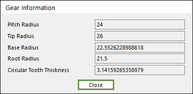
Figure 31.33 Gear Information dialog box
Draw: All data must be defined with respect to the tooth marker. You can move points graphically by using the mouse directly.
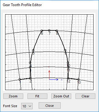
Figure 31.34 Gear Tooth Profile Editor dialog box
Generate optimal arc segment: In order to apply the modification of tooth, this button should be clicked.
Each Rendering: The selected mode can be displayed in Each Render mode.
Rotational Spring

Figure 31.35 Scissor Gear property page [Rotational Spring page]
The input values are same to Rotational Spring supported as a Force entity.
Translational Spring Input Option: Instead of inputting the stiffness coefficient for Rotational Spring, the user can input the calculated value from imaginary translational springs.
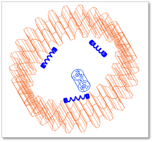
Figure 31.36 Imaginary Translational Springs
Spring Number: Enters the number of translational springs.
Radius: Enters the distance from the center.
Translational stiffness: Enters the spring stiffness of translational springs.
Update: The stiffness coefficient for Rotational Spring can be updated by clicking this button.
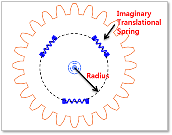
Figure 31.37 Input values for Imaginary Translational Spring
\(K=SpringNumber\times {Radius}^{2}\times TranslationalStiffness\)Eq 1. Equation of Rotational Spring Stiffness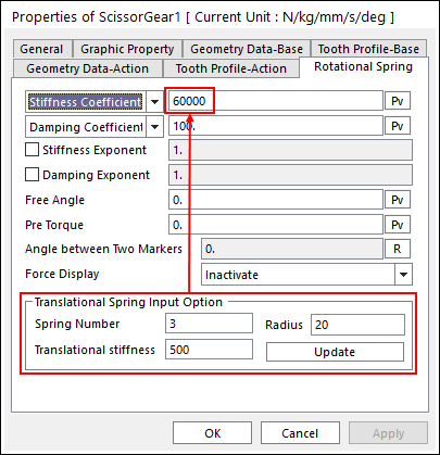
Figure 31.38 An example for Update