25.4.2. Movable Roller Group
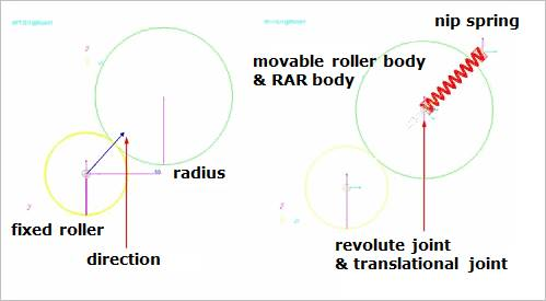
Figure 25.38 Movable roller group
25.4.2.1. Modeling Options
Fixed Roller Group, Direction, Radius
Fixed Roller Group: Selects a fixed roller group.
Direction: Defines the position of the movable roller group with respect to the fixed roller group.
Radius: Defines a radius of the movable roller group.
Fixed Roller Group, Direction, Radius, Distance
Fixed Roller Group: Selects a fixed roller group.
Direction: Defines the position of the movable roller group with respect to the fixed roller group.
Radius: Defines a radius of the movable roller group.
Distance: Defines an initial gap between the fixed roller group and the movable roller group.
Fixed Roller Group, Direction, Radius, Direction, Depth
Fixed Roller Group: Selects a fixed roller group.
Direction: Defines the position of the movable roller group with respect to the fixed roller group.
Radius: Defines a radius of the movable roller group.
Direction: Defines a depth direction of the movable roller group.
Depth: Defines a depth of the movable roller group.
Fixed Roller Group, Direction, Radius, Distance, Direction, Depth
Fixed Roller Group: Selects a fixed roller group.
Direction: Defines the position of the movable roller group with respect to the fixed roller group.
Radius: Defines a radius of the movable roller group.
Distance: Defines an initial gap between the fixed roller group and the movable roller group.
Direction: Defines a depth direction of the movable roller group.
Depth: Defines a depth of the movable roller group.
Body, Fixed Roller Group, Direction, Radius
Body: Selects a body to define the base body of the movable roller group.
Fixed Roller Group: Selects a fixed roller group.
Direction: Defines the position of the movable roller group with respect to the fixed roller group.
Radius: Defines a radius of the movable roller group.
Body, Fixed Roller Group, Direction, Radius, Distance
Body: Selects a body to define the base body of the movable roller group.
Fixed Roller Group: Selects a fixed roller group.
Direction: Defines the position of the movable roller group with respect to the fixed roller group.
Radius: Defines a radius of the movable roller group.
Distance: Defines an initial gap between the fixed roller group and the movable roller group.
Body, Fixed Roller Group, Direction, Radius, Direction, Depth
Body: Selects a body to define the base body of the movable roller group.
Fixed Roller Group: Selects a fixed roller group.
Direction: Defines the position of the movable roller group with respect to the fixed roller group.
Radius: Defines a radius of the movable roller group.
Direction: Defines a depth direction of the movable roller group.
Depth: Defines a depth of the movable roller group.
Body, Fixed Roller Group, Direction, Radius, Distance, Direction, Depth
Body: Selects a body to define the base body of the movable roller group.
Fixed Roller Group: Selects a fixed roller group.
Direction: Defines the position of the movable roller group with respect to the fixed roller group.
Radius: Defines a radius of the movable roller group.
Distance: Defines an initial gap between the fixed roller group and the movable roller group.
Direction: Defines a depth direction of the movable roller group.
Depth: Defines a depth of the movable roller group.
25.4.2.2. Properties
The user can modify the properties of the movable roller in this dialog box.
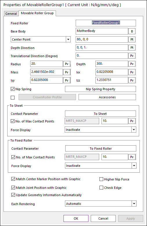
Figure 25.39 Movable Roller Group property page [Movable Roller Group page]
Fixed Roller: Shows the name of the dependent fixed roller.
Base Body: Defines the name of a carrier body that is connected to the RAR body with a translational joint.
Center Point [Reference Point]: Defines the center point of the roller body or reference point of a cylindrical geometry.
Depth Direction [Direction Point]: Defines the axial direction or direction point of the cylinder.
Translational Direction (Degree): Defines the translation direction. Default is 0.0 degree. The input angle range is from -90.0 to 90.0 degree. (Translation Direction effects the Soft Nip function. The moving direction of the Dummy body for the Soft Nip is the same with the Translation Direction. But, in the case of Maximum Gap, and Initial Gap functions are not related with this Translational Direction.)
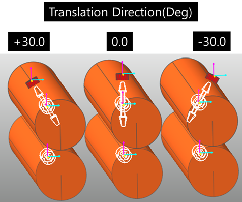
Figure 25.40 Effect of the Translation Direction
Radius: Defines the radius of the cylinder.
Depth: Defines the length of the cylinder.
Mass: Defines the mass of the roller body.
Ixx, Iyy, Izz: Defines the Moments of Inertia of the roller body.
Nip Spring: If it is checked, a spring force is active. You can modify the nip spring property by clicking Nip Spring Property.
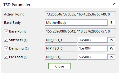
Figure 25.41 TSD Parameter dialog box
Action Point: Shows the point of the roller on the attached spring force.
Base Body: Defines the name of base body of the spring force.
Base Point: Shows the point of the base body on which the spring force is attached.
Stiffness: Shows the stiffness coefficient of the spring force.
Damping: Shows the damping coefficient of the spring force.
Pre Load: Shows the force applied when the length of the spring is zero.
CrownRoller Profile: When the roller shape is the crown roller type, this option is useful. The graphic and contact geometry of a roller is defined from Crown roller profile information.
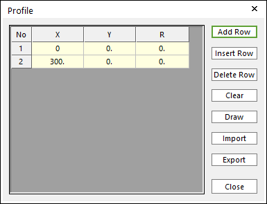
Figure 25.42 Profile dialog box of Crown roller
X,Y,R: Defines Points and radius.
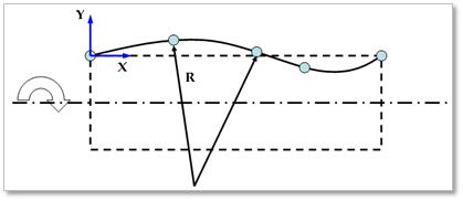
Figure 25.43 Definition of crown roller profile data
Add Row: Adds a row to the end of the table.
Insert Row: Inserts a row where the cursor is and move the current and later rows down.
Delete Row: Deletes the row where the cursor is and move the later rows up.
Clear: Deletes all rows in the table.
Draw: All data must be defined with respect to the center marker. You can move points graphically by using the mouse directly.
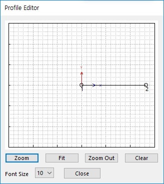
Figure 25.44 Profile Editor dialog box
Import: Imports the X, Y, and R data pairs from a CSV file or a MAT file or a text file. In the case of the text file, the usage of the comma, the tab, and the space can be the delimiter between the three columns in the file. And when using the Excel file, the user can select the Tab-delimited text file output option or the CSV (Comma-Separated Values) file output option to save the Excel file which can be imported.
Export: Exports the X, Y, and R data pairs to a CSV file or a MAT file or a text file.
Accessories: Accesses the dialog box defining Soft Nip, Motion and Maximum Gap.
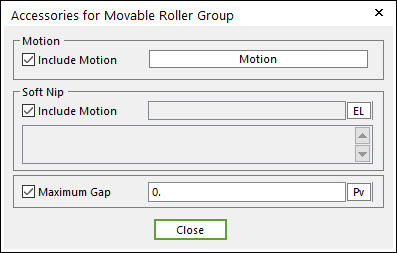
Figure 25.45 Accessories for Movable Roller Group dialog box
Include Motion: Shows the Angular motion of the Movable Roller. You can define the roller displacement, velocity and acceleration by using a Expression. Refer to Motion.
Soft NIP: Shows the displacement of the Movable roller. You can adjust a gap between two rollers by using a Expression.
Maximum Gap: Shows the limitation of maximum gap between the Movable roller and the Fixed roller.
Contact Parameter: Allows the user to modify contact parameters by clicking To Sheet and To Fixed Roller.
To Sheet: In this dialog box, the user can modify the contact parameters of contact forces applied between the sheet and the fixed roller. Refer to Contact Formulations for MTT3D.
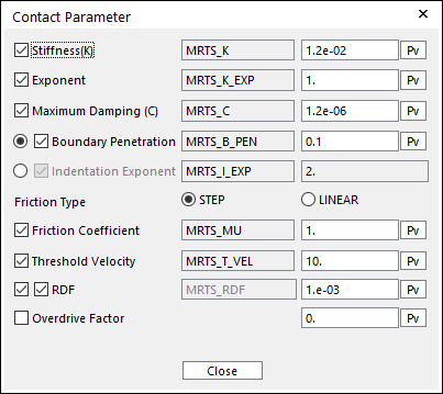
Figure 25.46 Contact Parameter dialog box
To Fixed Roller: In this dialog box, the user can modify the contact parameters of contact forces applied between the movable roller and the fixed roller. Refer to Contact Formulations for MTT3D.
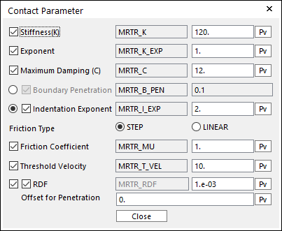
Figure 25.47 Contact Parameter dialog box
No. of Max Contact Points (To SHEET and To FIXED ROLLER): Defines the number of max contact point for output. User can define this value from 1 to 5000. This value only affects Force Display and RPLT data about the contact points. The default value is 10.
Force Display (To SHEET and To FIXED ROLLER): Graphically displays the all contact force vectors (the sum of the normal and tangential contact force) at each contact point up to the No. of Max Contact Point.
Match Center Marker Position with Graphic: Match the position and orientation of the center marker of the roller body with the geometry reference frame.
Match Joint Position with Graphic: Match the positions and orientations of the markers of the revolute joint with the geometry reference frame.
Use Higher Nip Force: When the user applies a higher nip force on the movable roller, you have to check this option. If the nip force is larger, the contact normal force of the roller to roller contact may be continuously generated although the sheet is passing between the rollers. If the nip force is over 1 Newton, the option would like to be turned on.
Check Edge: When the roller is smaller than the lengths of a contacted shell element, the contact doesn’t work. In this case, if this option is ON, the two end sides and center of the roller are checked in the sheet-to-roller contact. The contact geometry of the roller is represented as three circles. And contact search of the inner contact point option for the sheet doesn’t do.
Update Geometry Information Automatically: If this option is unchecked, the position and orientation of the geometry constituting the group are not updated depending on variables in the property page. So, after executing Extract function, this option is unchecked.
Each Rendering: The selected mode can be displayed in Each Render mode.