6.3.3.4. Tire
A Tire force generates a force for the tires of car. Also, it can be defined by the user subroutines. RecurDyn supports tire types as shown in Figure 6.280.
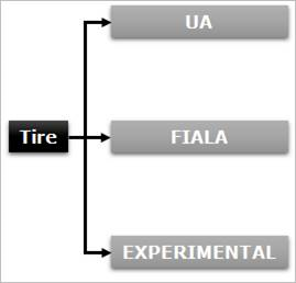
Figure 6.280 Tire Types in RecurDyn
Before starting the modeling by using a tire force, the user should be careful for the followings.
When generating a tire force, the direction of gravity force must be changed to the z-axis.
When creating a tire body, the user must create the body in the xz plane.
The z-axis of the tire force becomes rotational axis of the tire.
The orientation of center marker of tire body must be same as the orientation of the action marker of the tire force.
Step to Create Tire Force
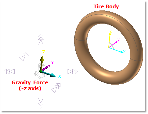
Figure 6.281 Creation of the Tire Force
Change the gravity force as -Z axis
Change the working plane as XZ plane. If the working plane is the XY plane, click the Change to Bottom of Working Plane Change toolbar and the working plane is changed to the XZ plane.
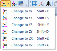
Figure 6.282 Change to XZ plane
Create a tire body by using the entities of Body group in the Professional tab.
To generate a tire force, change the working plane to the XY plane.
Click the Tire icon of the Force group in the Professional tab
Click 1 point and 2 point. The z axis of the tire force is defined by the two points.
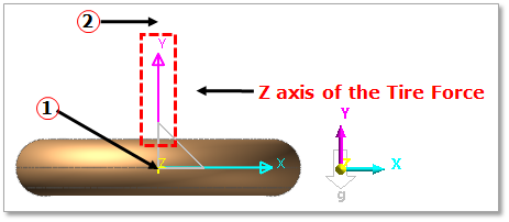
Figure 6.283 Generation of the Tire Force
Copy the orientation of tire force marker.
Open the properties dialog box of the tire body.
Change Material Input Type from Library to User Input, and then click Apply.
Click CM.
Paste the orientation (Euler Angle) from the tire force orientation.
Note
The orientation of the tire body and the tire force should be same.
6.3.3.4.1. Modeling Options
The user can create a force entity as follows.
Point, Direction
Point: Selects a point for the tire center position.
Direction: Defines the z-axis of the tire. The z-axis is the rotational axis of the tire.
Point
Point: Selects a point for the tire center position.
Body, Point, Direction
Body: Selects a body for the tire.
Point: Selects a point for the tire center position.
Direction: Defines the z-axis of the tire. The z-axis is the rotational axis of the tire.
Body, Point
Body: Selects a body for the tire.
Point: Selects a point for the tire center position.
Solid(Shell), Solid(Shell), Point, Direction
Solid(Shell): Selects a solid or shell to define a base solid for Solid Contact.
Solid(Shell): Selects a solid or shell to define an action solid for Solid Contact.
Point: Selects a point for the tire center position.
Direction: Defines the z-axis of the tire. The z-axis is the rotational axis of the tire.
Solid(Shell), Solid(Shell), Point
Solid(Shell): Selects a solid or shell to define a base solid for Solid Contact.
Solid(Shell): Selects a solid or shell to define an action solid for Solid Contact.
Point: Selects a point for the tire center position.
6.3.3.4.2. Properties
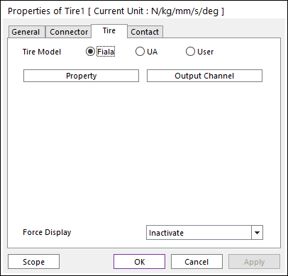
Figure 6.284 Tire property page
Tire Model: Select a tire model of the following types. The Fiala model and UAtire model require the simpler data than the experimental model does.
Fiala: Allows the user to define a tire model as Fiala. Refer to Fiala Tire Model.
UA: Allows the user to define a tire model as UA. Refer to UATire Model.
User: Allows the user to define a tire model by an expression.
Property: Includes the tire physical property.
Output Channel: Check this to plot outputs. If the user checks this, the user can see the output data in Plot Window after analysis.
Force Display: Displays the resultant force vector graphically on Working Window.