9.9.11. Cylinder To FSurface Contact
Cylinder To FSurface Contact generates a contact force between a FFlex body and a Rigid body.
The FFlex body is the base body of contact and the rigid body is the action body.
The Patch Set of base contact surface must be defined before creating the contact.
The patch set should be generated on the FFlex body.
The contact force is generated with the compliance characteristics allowing to the penetration.
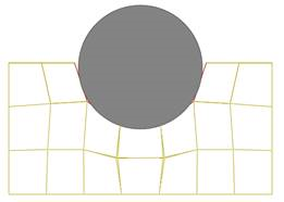
The action contact geometry is defined as a cylinder and the base contact surfaces are approximated as multi-triangular or rectangular patches according to the finite element as shown in Figure 9.145.
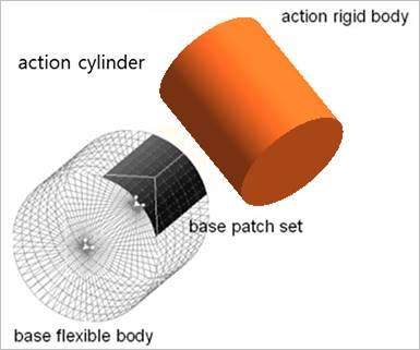
Figure 9.145 Contact geometry
Contact points
The cylinder of action body is examined whether it is contacted with the base patches.
9.9.11.1. Modeling Options
Patch Set, Cylinder
Patch Set, MultiCylinder
Patch Set, Cylinder Patch Set, Cylinder
MultiPatch Set, MultiCylinder
9.9.11.2. Properties
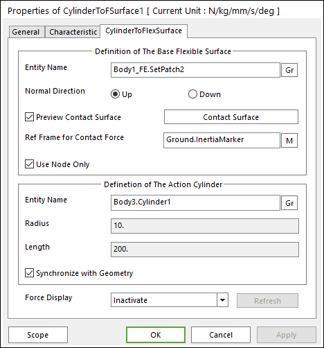
Figure 9.146 CylinderToFSurface property page
Definition of the Base Flexible Surface
Entity Name: Defines the name of base patch set. The base patch set is dispatched from the screen by clicking Gr.
Normal Direction: Is the normal direction of base patch set for a contact.
The contact is available in the specified direction.
As selecting Up or Down, the user can change the contact direction of a base geometry.
If this page is activated, the normal direction is automatically shown on the Working Window.
Preview Contact Surface: If this option is checked, the patches making the contact surface and its boundary box are highlighted.
Contact Surface: Accesses the Contact Surface dialog box. For more information, click here.
Ref. Frame for Contact Surface: The contact force applied on the base body is reported as a force generalized on the defined marker. If the marker is not defined, the default is Ground.Inertia Marker.
Use Node Only: Nodes of base flexible contact surface are only used to generate the contact force of Cylinder To FSurface contact. Generally, this option can be very useful for accuracy and solving speed in the following case.
If the user does not use this option, the contact is applied as patch shape only.
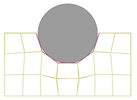
If the user uses this option, the contact is applied as flexible body shape more correctly.
Definition of the Action Cylinder
Entity Name: Defines the name of the action patch set. The action patch set is dispatched from the screen by clicking Gr.
Radius: Defines the radius of action sphere. This value is automatically determined by the radius of the action geometry but if the user turns off the Synchronize with Geometry option, the user can directly input the radius or change it as the parametric value by clicking PV.
Length: Defines the height of action cylinder. This value is automatically determined by the height of the action geometry, but if the user turns off the Synchronize with Geometry option, the user can directly input the height or change it as the parametric value by clicking PV.
Synchronize with Geometry: If this option is checked, the contact radius of circle or sphere is automatically defined with that of the specified graphic.
Force Display: The user can graphically display the resultant force vector on the working window.
Refresh: When the action contact patch set or base contact patch set is changed, the user can refresh the preview of information of specified contact patch set by this function.