6.2.2.8. Universal
An universal joint provides the proper kinematics for joining two yoke bodies through a cross-shaped link as shown in the Figure 6.197. This joint has two rotational degrees of freedom, namely the rotations about the two cross axes. It is especially effective when transferring rotational motion around corners, when the user needs to simulate the non-constant velocity of a physical universal joint, or when transferring rotational motion between two connected shafts that are permitted to bend at the connection point (such as the drive shaft on an automobile). The location point of the universal joint displays the connection point of the two parts. For a universal joint, the cross bars identify the axes about which the two parts are permitted to rotate with respect to each other. The z-axis for each yoke marker is oriented along the corresponding rotational axis for the cross. The x-axis for each yoke marker is oriented along the centerline of the yoke.
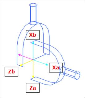
Figure 6.197 Universal Joint icon on Working Window
6.2.2.8.1. Modeling Options
The user can create a joint entity as follows.
Point, Direction, Direction
Point: Selects a point on two bodies to define the location of the universal joint.
Direction: Defines the z-axis of the base marker, which should be oriented along one of the rotational axes of the cross. The x-axis of the base marker is defined to be orthogonal to the z-axis of the base marker at once.
Direction: Defines the z-axis of the action marker, which should be oriented along the other rotational axis of the cross. The x-axis of the action marker is defined to be orthogonal to the z-axis of the action marker, as explained in the description of the universal joint. If the user wants to define the orientation of the z-axis to be normal on the screen, click the same position as the origin of the universal joint.
Body, Body, Point, Direction, Direction
Body: Selects a base body of universal joint.
Body: Selects an action body of universal joint.
Point: Selects a point to define the location of the universal joint.
Direction: Defines the z-axis of the base body, which should be oriented along one of the rotational axes of the cross. The x-axis of the base body is defined to be orthogonal to the z-axis of the base body at once.
Direction: Defines the z-axis of the action marker, which should be oriented along the other rotational axis of cross. The x-axis of action marker is defined to be orthogonal to the z-axis of the action marker, as explained in the description of the universal joint. If the user wants to define the orientation of the z-axis to be normal on the screen, click the same position as the origin of the universal joint.
Point, Direction, Direction, Direction, Direction
Point: Selects a point on two bodies to define the location of the universal joint.
Direction: Defines the z-axis of the base marker.
Direction: Defines the x-axis of the base marker.
Direction: Defines the z-axis of the action marker.
Direction: Defines the x-axis of the action marker.
Body, Body, Point, Direction, Direction, Direction, Direction
Body: Selects a base body of universal joint.
Body: Selects an action body of universal joint.
Point: Selects a point to define the location of the universal joint.
Direction: Defines the z-axis of the base marker.
Direction: Defines the x-axis of the base marker
Direction: Defines the z-axis of the action marker.
Direction: Defines the x-axis of the action marker.
6.2.2.8.2. Properties
The user can define friction force using the Joint page.
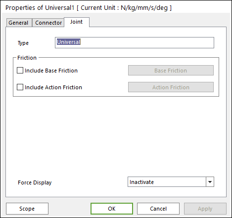
Figure 6.198 Universal property page [Joint page]
Type: Shows the type of joint.
Friction: Defines the friction force which contains a sliding and stiction algorithm on the universal joint. The check box for Include Friction in the Joint property page must be checked to use the friction force. The joint friction of the universal joint is the same as Revolute Joint. Refer to Joint Friction.
Include Base Friction: The base friction is applied to the base body.
Include Action Friction: The action friction is applied to the action body.
Force Display: Displays the resultant force vector graphically on Working Window.