where, \(\mathbf{k}\) and \(\mathbf{c}\) are the stiffness and damping coefficients which are determined by an experimental method, respectively.
\(\delta\) and \(\dot{\delta}\) are a penetration and time differentiation of the penetration, respectively.
The exponents \({m1}\) and \({m2}\) generates a non-linear contact force and the exponent \({m3}\) yields an indentation damping effect.
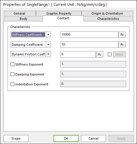
Characteristic: Defines the contact properties such as the stiffness coefficient, damping coefficient, and friction coefficients. Also, these coefficients can be given as user-defined spline curves.
Stiffness Coefficient: Specifies a stiffness coefficient for the contact normal force.
Stiffness Spline: The spline shows the contact normal force for the penetration. For more information, click here.
Damping Coefficient: Specifies a damping coefficient for the contact normal force.
Damping Spline: The spline shows the contact normal force for the velocity of penetration. For more information, click here.
Dynamic Friction Coefficient: Specifies a dynamic friction coefficient for the contact friction force. It has three options.
Dynamic Friction Coefficient: The constant friction coefficient is applied.
Friction Force Spline: The spline shows the fiction force for the relative velocity. It is recommended to use the spline that x and y values are defined as positive.
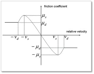
Friction Coefficient Spline: The spline shows the friction coefficient for the relative velocity.
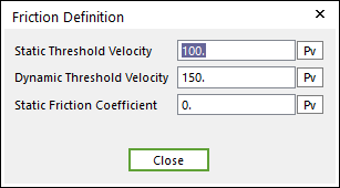
More: Specifies some friction coefficients for the contact friction force.
Stiffness and Damping Exponent: Generates a non-linear contact normal force.
Indentation Exponent: Yields an indentation damping effect. When the penetration is very small, the contact force may be negative due to a negative damping force, which is not realistic. This situation can be overcome by using the indentation exponent greater than one.
Contact Output File: When this function is checked, RecurDyn creates the contact output file for contact information between sprocket and track links as follows. (Please refer to this option only output the results for track links, they checked at Output page in assembly information). The name of output file is ModelName_ContactName.out.
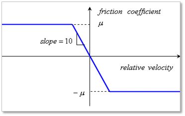
Dynamic Threshold Velocity: If the relative velocity between a contact pair is greater than this value, the friction coefficient is same as the specified dynamic friction coefficient. If the relative velocity between a contact pair is greater than “Static Threshold Velocity” and less than this value, the friction coefficient is defined as following.
where, \({{f}_{n}}\), \(\mu (v)\), and \({{f}_{\max }}\) are the contact normal force, the friction coefficient, and the maximum friction force, respectively. The friction coefficient of \({{f}_{f}}\) is determined by a relative and tangential velocity on the contact point as shown in Figure 28.6.