6.4.4.4. CamLine 2D
A CamLine2D Contact generates a force between a line with two points and a curve. This contact is smooth line to curve contact in 2D. The base curve has a RM and many points. The action line has a RM and its radius. The base curve is parameterized from many points and creates a contact curve fitted on a cubic spline or a fifth order polynomial.
The line and the curve must belong to two different bodies.
The base curve should be a close curve as like as cam geometry.
This contact point is only one point where a contact penetration is the deepest.
The contact force can be not only linear or exponential but also nonlinear spline characteristics to the contact penetration and its velocity.
The base curve is a curve fitted to passing points as shown in Figure 6.395.
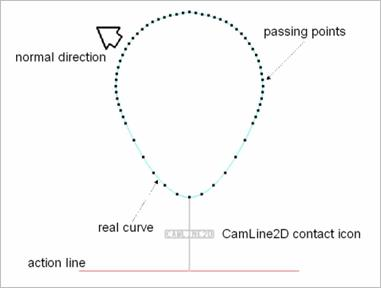
Figure 6.395 CamLine2D Contact
6.4.4.4.1. Modeling Options
In the case of CamLine2D contact, a line geometry type is supported for an action geometry and a curve geometry type is supported for a base geometry when creating.
Curve, Line
Curve: Selects a curve to define a base curve.
Line: Selects a line to define an action line.
Curve, MultiLine
Curve: Selects a curve to define a base curve.
MultiLine Selects some lines to define action lines.
Curve, Line, Curve, Line
Curve: Selects a curve to define a base curve.
Line: Selects a line to define an action line.
Curve: Selects a curve to define another base curve.
Line: Selects a line to define another action line.
MultiCurve, MultiLine
MultiCurve: Selects some curves to define base curves.
MultiLine: Selects some lines to define action lines.
6.4.4.4.2. Properties
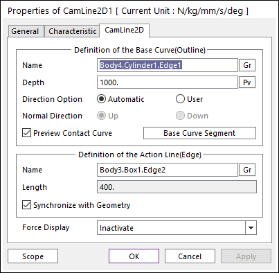
Figure 6.396 Properties of CamLine2D dialog box
Definition of The Base Curve (Outline)
Entity Name: Defines the name of base curve or outline. The base curve or outline can be dispatched from the Working Window by clicking Gr.
Depth: Defines the depth of contact face of the base curve. The user can change the depth as the parametric value by clicking PV.
Normal Direction: Defines the normal direction of base curve or outline for a contact.
The contact is available in the specified direction.
As selecting Up or Down, the user can change the contact direction of a base geometry.
If this page is activated, the normal direction is automatically shown on the Working Window.
Preview Contact Curve: If this option is checked, the points making the contact curves are shown on the Working Window.
Base Curve Segment: Accesses Base Curve Segment dialog box. For more information, click here.
Definition of the Action Line(Edge)
Entity Name: Defines the name of action outline with two points or edge of a solid. The user can change the action line by using the navigation method.
Length: Shows the length of action line. This value is automatically determined by the length of the action line but if the user doesn’t check the Synchronize with Geometry option, the user can directly input the length or change it as the parametric value by clicking PV.
Synchronize with Geometry
If this option is checked, Length in contact properties is automatically defined with that of the specified graphics.
If this option is not checked, the user can modify the contact properties.
Force Display: Graphically displays the resultant force vector on the view window.