23.2.3.1.3. Walls
A co-simulation between RecurDyn and a particle solver requires that walls are created. There must be at least one wall for each particle solver included in a co-simulation. If no walls are created for a particular particle solver in a RecurDyn model, then RecurDyn does not attempt to co-simulate with that particle solver. A wall is created from one or more geometry of a RecurDyn body. In the particle solver, these geometries become a wall. Particles in the particle solver make contact with the wall. Particles apply either contact forces or pressure forces to walls when they are in contact. The particle forces acting on the wall are returned from the particle solver to RecurDyn. RecurDyn applies the forces to the RecurDyn body that the wall is attached to.
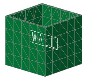
Figure 23.44 Wall example
23.2.3.1.3.1. Modeling Options
The user can create a wall as follows.
Body
Body: Select a body.
Surface(PatchSet)
Surface(PatchSet) : Select a surface on a body or a patch set generated from flexible body.
Solid(Shell,PatchSet)
Solid(Shell,PatchSet): Select a solid body or a patch set generated from flexible body.
MultiSolid(Shell)
MultiSolid(Shell): Select several solid geometries.
Assembly
Assembly: Select TPart assembly (Track HM/LM, Chain, Segment type Belt).
23.2.3.1.3.2. Properties
The user can modify the properties of wall in the following dialog box.
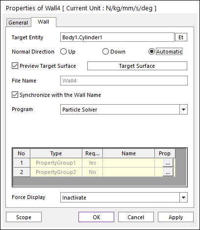
Figure 23.45 Wall property page for the Rigid Wall
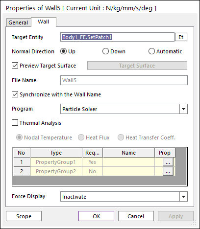
Figure 23.46 Wall property page for the Flexible Wall
Target Entity: Displays the selected geometry or body.
Normal Direction: Defines the contact side of the wall.
Whether or not an option is supported is depending on the particle solver.
Only the Normal Directions supported by the particle solver is shown.
As selecting Up or Down or Automatic, the user can change the contact side of wall.
Preview Target Surface: If it is checked, the user can visually verify which side is the contact side if Up or Down is selected. The vectors in the Working Window point to the side on which the particles are able to make contact. The Automatic Normal Direction indicates that the particle solver uses its own algorithm to determine the contact side. Please see the particle solver’s documentation to determine the meaning of this selection.
Target Surface: Sets the mesh size of wall.
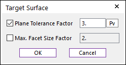
Figure 23.47 Target Surface dialog box
Plane Tolerance Factor: Specifies the surface tolerance factor as a value from 0 to 10. A smaller value produces a more refined patch. For more information, click here.
Max. Facet Size Factor: Specifies the max.facet size factor as a value from 0 to 10. This value controls the maximum size of triangular patch length. To see more information, click here.
Synchronize with the Wall Name: If this option is checked, File Name is the same as the wall name. If it is unchecked, the user can input an arbitrary name into the File Name text field.
Program: The connected particle solver is shown. The user can choose to use this wall for a different particle solver.
Thermal Analysis : This option is only available for the Flexible Wall and the API version 1030 or higher. If the check box is unchecked than the flexible wall is defined as an isolation boundary condition.
Nodal Temperature : RD computes the structural-thermal analysis with transferred the nodal temperatures from the particle solver. Both constant and variable temperatures are available. This option can be used for isothermal boundary condition.
Heat Flux : RD computes the structural-thermal analysis with transferred the nodal heat fluxes from the particle solver. RD gives the nodal temperature to the particle solver. This option can be used for external heat source.
Heat Transfer Coeff. : RD computes the structural-thermal analysis with transferred the nodal heat transfer coefficients and ambient temperatures from the particle solver. RD gives the nodal temperature to the particle solver. This option can be used for convection.
Properties: The material properties of particle set.
Type: The type of the property group have to set.
Required: If the Required flag is Yes, then the specified property type element is required for particle sets. If it is No, then the specified property type element is optional for particle sets.
Name: The name of selected property group.
Prop.: The user can open the Property Groups dialog box by clicking the … buttons in the Prop. and also can set the property group using it.
Force Display: Graphically displays the resultant force vector on the view window.