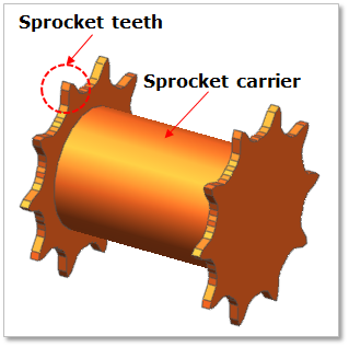
In general, a high mobility tracked vehicle employs double sprockets interconnected by sprocket carrier. Exact sprocket tooth geometry can be defined. The sprocket tooth geometry data can be created, edited, or imported from a predefined data file.
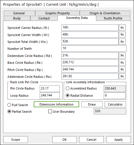
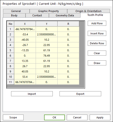
Figure 27.9 Sprocket property page [Geometry Data page]
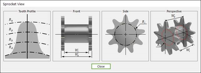
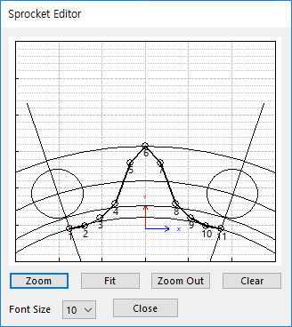
The Sprocket property page is shown in Figure 27.9. The parameters are explained below. In order to understand the geometry, refer to Dimension Information.
Sprocket Carrier Radius (Ri): Enters the carrier radius of sprocket.
Sprocket Carrier Width (Wi): Enters the carrier width of sprocket.
Sprocket Total Width (Wo): Enters the total width of sprocket.
Number of Teeth: Enters the number of teeth.
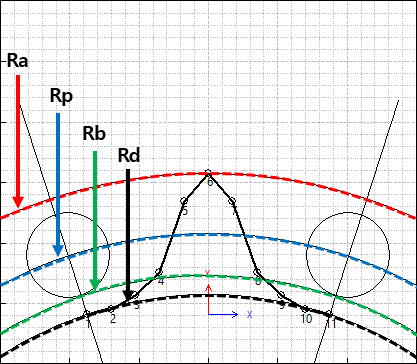
Dedendum Circle Radius (Rd): Enters the dedendum circle radius of tooth profile.
Base Circle Radius(Rb), Pitch Circle Radius(Rp), Addendum Circle Radius(Ra): These values can help to modify the shape of sprocket tooth easily as baseline in Sprocket Editor dialog and it is used in the TVLM Calculator dialog. It does not change the sprocket geometry directly.
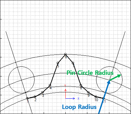
Pin Circle Radius, Loop Radius: These data must be defined with respect to the sprocket tooth marker. And these values can help to modify the shape of sprocket tooth easily as baseline in Sprocket Editor dialog and it is used in the TVLM Calculator dialog. It does not change the sprocket geometry directly.
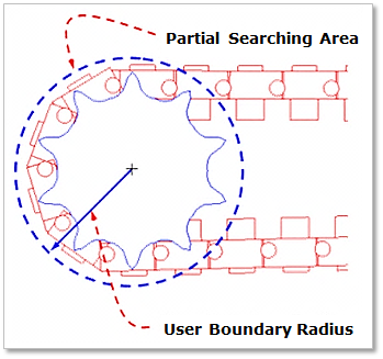
Partial Search: Some links are searched for contact in some boundary. It is used to reduce total solving time.
User Boundary: In the case of Partial Search, the search boundary can be modified.
Figure 27.13 Partial searching area & user boundary
Note
When the user checks Partial Search, searching for contact of between a sprocket and links is available in specific boundary. It is used to reduce total solving time. If the user checks User Boundary, the user can change the value of boundary radius.
And if the user does not use it, the value of boundary radius is set internally.
Import: Imports the X, Y, and R data pairs from a CSV file or a MAT file or a text file. In the case of the text file, the usage of the comma, the tab, and the space can be the delimiter between the three columns in the file. And when using the Excel file, the user can select the Tab-delimited text file output option or the CSV (Comma-Separated Values) file output option to save the Excel file which can be imported.
Export: Exports the X, Y, and R data pairs to a CSV file or a MAT file or a text file.
Contact between a Sprocket and Track Links
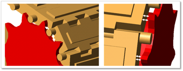
During the course of engagement between the sprocket teeth and the track links, several sprocket teeth can be in contact with several track links pins, as shown in Figure 27.16. A Cartesian coordinate system is introduced for each contact surface. The surface coordinate system is assumed to have a constant orientation with respect to a selected tooth coordinate system. The tooth coordinate system has a constant orientation with respect to the coordinate system of the sprocket. Therefore, the orientation of a surface coordinate system can be defined in the global system using three coordinate transformation matrices; two of them are constant and the third is the time dependent rotation matrix of the sprocket. Using these coordinate transformations and the absolute Cartesian coordinates of the origin of the sprocket coordinate system, the location and orientation of each tooth surface can be defined in the global coordinate system. Using the track link coordinate system, the global position vector of the center of the track link pin can be defined. This vector and the global coordinates of the tooth surfaces can be used to determine the position of the track link pins with respect to the sprocket teeth. The relative position of the track link pins, with respect to the sprocket teeth can be used to develop a computer algorithm that determines whether or not the track link pin is in contact with one of surfaces of the sprocket teeth.
(a) Sprocket teeth and pin contact (b) Teeth side wall and link side wall contact
Figure 27.16 Sprocket tooth and track interactions