6.1.4.9. Simplify
Users can simply a geometry using the Delete Face and Delete Edge functions. Imprinted edges could be deleted using the Delete Edge function. Hole, Cylinder, and Fillet (round) type faces could be deleted using Delete Face function.
6.1.4.9.1. Delete Face
It allows the user to simplify a solid and surface geometric entity by deleting the faces of the geometry.
Modeling Option
The user can simplify one geometric entity by the following procedure.
Solid(Sheet), MultiFace
Solid(Sheet): Selects a solid or sheet geometry. And then the Delete Faces Operation dialog box appears.
MultiFace: Selects several faces of the selected geometry. The faces are deleted by clicking OK in the Delete Faces Operation dialog box.
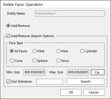
Figure 6.132 Delete Faces Operation dialog box
Entity Name: Shows the name of the selected entity.
Add/Remove: Selects several faces of the selected entity as the user wants to add or remove.
Add/Remove (Search Option): If it is checked, other advanced search options could be used.
Face Type: Specific types of faces are searched and selected.
Min. Size, Max. Size, Cal.: After selecting a type of Face Type, Min. Size and Max. Size of the specific type of faces is shown by clicking Cal.. These are references to set the Size Tolerance value.
Size Tolerance: If it is checked, faces of the specified type less than the tolerance value are searched and selected by clicking Search.
6.1.4.9.2. Delete Edge
It allows the user to simplify a solid and surface geometric entity by deleting edges of the geometry.
Modeling Option
The user can simplify one geometric entity by the following procedure.
Solid(Sheet), MultiEdge
Solid(Sheet): Selects a solid or sheet geometry. And then the Delete Edges Operation dialog box appears.
MultiEdge: Selects several edges of the selected geometry. The edges are deleted by clicking OK in the Delete Edges Operation dialog box.
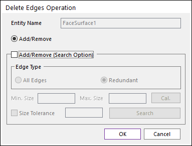
Figure 6.133 Delete Edges Operation dialog box
Entity Name: Shows the name of the selected entity.
Add/Remove: Selects several edges of the selected entity as the user wants to add or remove.
Add/Remove (Search Option): If it is checked, other advanced search options could be used.
Edge Type: Specific types of faces are searched and selected.
Min. Size, Max. Size, Cal.: After selecting a type of Edge Type, Min. Size and Max. Size of the specific type of edges is shown by clicking Cal. These are references to set the Size Tolerance value.
Size Tolerance: If it is checked, edges of the specified type less than the tolerance value are searched and selected by clicking Search.
6.1.4.9.3. Fill Hole
It allows the user to fill the empty region of the geometries.
Modeling Option
The user can fill holes in one geometric entity by the following procedure.
Solid(Sheet), WithDialog
Solid(Sheet): Selects a solid or sheet geometry. And then the Fill Hole Operation dialog box appears.
WithDialog: Selects several edges or faces. The selected holes are filled by clicking OK in the Fill Holes dialog box.
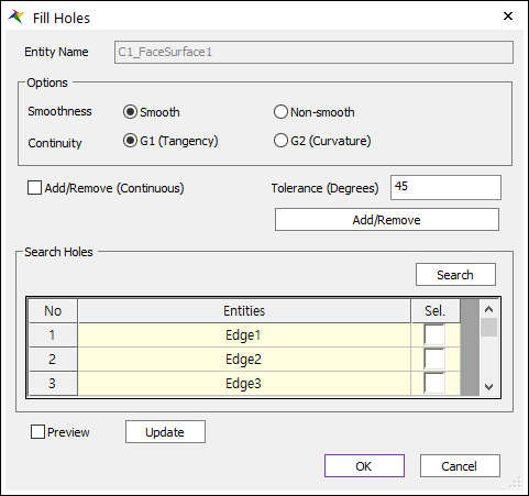
Figure 6.134 Fill Hole dialog box
Entity Name: Shows the name of the selected entity.
Smoothness: Selects the surface to fill the holes and whether the created surface connected to the faces smoothly.
Continuity: Selects whether the surface to fill the holes is G1 or G2 smooth at the boundary edges.
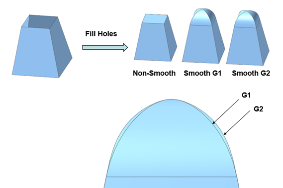
Figure 6.135 Smoothness and Continuity of Fill Holes
Non-Smooth G0: The surface has the continuous position. Faces are connected and have no gaps.
Smooth G1: The surface has the continuous normal and the same tangent at the connected part.
Smooth G2: The surface has continuous curvature.
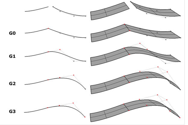
Figure 6.136 Continuity of a curve and a surface
Add/Remove: If the selected geometry is a surface, the edges around the hole should be selected. If the selected geometry is solid, the faces should be selected. The selected faces are deleted, and the hole is filled with the new faces.
Add/Remove (Continuous): When using Add/Remove, if this option is checked, the connected faces within the degrees are selected together.
Tolerance (Degrees): The angle between the connected two faces.
Search Holes: Searches all the edges around the holes. The edges are selected by checking the checkbox in the grid. (This function is available only with the surface geometries.)
Preview: Previews that the holes are filled on Working Window.
Update: Updates the preview.