25.3. Sheet Shell
Coordinate System
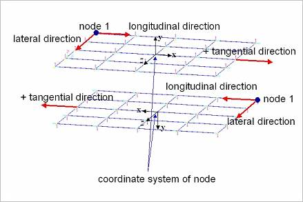
Figure 25.10 Coordinate system of the sheet body
The node is described as a sphere and the center marker is located at the central point of the sphere and its orientation is dependent on a direction used when the sheet is created as shown in Figure 25.10.
The x-axis of the center marker is determined in the same direction with the longitudinal direction.
The z-axis of the center marker is determined in the same direction with the lateral direction
The y-axis is automatically determined by the right-hand rule.
If the user applies a plus value in the initial velocity of sheet, the sheet moves into the plus direction of the x-axis of the center marker for each sheet body. The plate force markers of each sheet body are located at the center marker and their orientations are the same orientation of each center marker.
Note
In the case of Surface Type sheet, the rule to define orientation of the center marker is different.
The x-axis of the center marker is determined to the direction of the first curve.
The z-axis of the center marker is determined to the direction from the first curve to the second curve.
The y-axis is automatically determined by the right-hand rule.
Nodal Masses and Moments of Inertia of Sheet Body
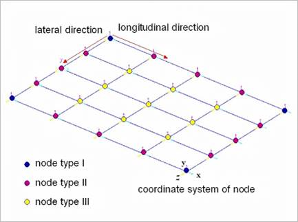
Figure 25.11 Nodal Masses and Moments of Inertia
Total mass (M):
\(M=density(\rho)*volume(V)\)
Mass coefficient (m):
\(m=\frac{M}{1+n_1n_2-n_1-n_2}\)
\({{n}_{1}}\): the number of nodes in the longitudinal direction
\({{n}_{2}}\): the number of nodes in the longitudinal direction
Moments of Inertia (I):
\(I=\left[ \begin{matrix} \frac{m}{12} \left[ \left( \frac{L_2}{n_2-1} \right)^2 +h^2 \right] & 0 &0 \\ 0 & \frac{m}{12} \left[ \left( \frac{L_2}{n_2-1} \right)^2 + (\frac{L_1}{n_1-1})^2 \right] & 0 \\ 0 & 0 & \frac{m}{12} \left[ \left( \frac{L_1}{n_1-1} \right)^2 +h^2 \right] \end{matrix} \right]\)
\({{L}_{1}}\): the length of the sheet in the longitudinal direction
\({{L}_{2}}\): the length of the sheet in the lateral direction
Nodal masses:
\(TypeI=\frac{m}{4}\) for nodes at four corners
\(TypeII=\frac{m}{2}\) for nodes on four edges
\(TypeIII=\,m\) for internal nodes
Nodal moments of inertia:
\(TypeI=\frac{m}{4}\) for nodes at four corners
\(TypeII=\frac{1}{2}\) for nodes on four edges
\(TypeIII=I\) for internal nodes
Curl radius of Sheet in 3D
The sheet can have curl radius in two directions as shown in Figure 25.12.
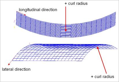
Figure 25.12 Sheet curl radius in two directions
Contact geometry of Sheet
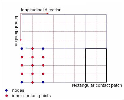
Figure 25.13 Contact geometry of Sheet
The contact geometry of sheet is approximated as the rectangular contact patches as shown in Figure 25.13. A rectangular contact patch means a sheet element. If the inner contact point has a value not zero, each rectangular patch is divided to some rectangular patches. In the Figure, the sheet is meshed 5 by 3 in longitudinal and lateral directions and each number of inner contact points in the two directions is 3 and 1, respectively.
The parameters used to define the contact between the sheet and the rollers and guides can significantly influence the solving time of a model. Because of the very small masses in a sheet, the contact force is very sensitive to contact parameters. Higher stiffness and damping values can reduce numerical stability. Because of this reason, the default sheet contact stiffness is set to a low value. For the same reason (small mass of sheet segments), the contact damping parameter should be set to a small value for numerical stability. A good practice is to set the damping constant relative to the mass of the sheet segments. The default ratio is 0.01% of the mass of the individual sheet node.