28.4.1. Modeling Options
Click the Assembly icon of the Assembly group in the Track(LM) tab and select a set of track bodies with which the track chain makes contact. Whenever the user moves the mouse, the underling body is highlighted and the user sees a solid line connecting the previously selected body and the highlighted body. After completing a closed chain, the following dialog box for the track chain pops up.
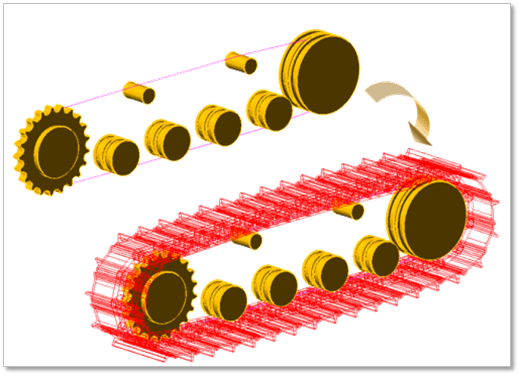
Figure 28.79 Track assembly
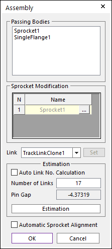
Figure 28.80 Track chain system dialog box
If needed, the user enters the number of track links and clicks Estimation. The user can compute the approximate pre-tension between track links from the estimated track gap.
If ‘Automatic Sprocket Alignment’ is checked, the sprockets are rotated to match the position of the links.
If uses used Automatic Sprocket Alignment, the dimensions of the model must be correct.
If user uses Automatic Sprocket Alignment, no interference must be between a sprocket and a link.
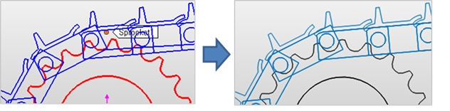
Figure 28.81 After using Automatic Sprocket Alignment option
Click OK, then the Track assembly is completed.
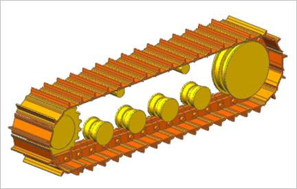
Figure 28.82 Completed Track assembly
28.4.1.1. Assembly dialog box
During assembly, a below dialog box is shown.
Figure 28.83 Assembly dialog box
Passing Bodies: Shows the list of assembled bodies.
Sprocket Modification: Modifies the assembly information about Sprocket. For more information, click here.
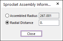
Figure 28.84 Sprocket Assembly Information dialog box
Link: Selects a clone link. If the user clicks Set, the user can customize the generated link set.
Set: The user can use link sets wanted among the defined link sets. To use this function, the user must define link sets when creating clone of a link. For more information, click here.
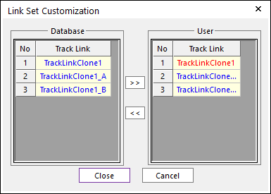
Figure 28.85 Link Set Customization dialog box
Link Set Customization
The user cannot move the first link and can compose user’s link by the database’s link.
The composed link set is marked in the RMD file.
Estimation: The user can estimate the assembled links.
Auto Link No. Calculation: If the user clicks Estimation with the checked this option, the number of links is set automatically.
Number of Links: Modifies the number of links.
Pin Gap: Shows a value of pin gap.
Automatic Sprocket Alignment: If this option is checked, the sprockets are rotated to match the position of the links.
Figure 28.86 After using Automatic Sprocket Alignment option
Note
If there are interference between a sprocket and a link after finishing assembly with this option, the alignment is failed.
Tip