25.3.2. Properties
The Sheet Shell property page is shown in Figure 25.17. And its parameters are explained below. The user can modify properties for the sheet shell such as geometry information, FFlex body characteristics, boundary condition, and output. The general pages such as General Page, Graphic Property Page, Origin and Orientation Page are same with general body.
FE Info (Refer to FEInfo. in FFlex)
Connecting Parameter (Refer to Connecting Parameter in FFlex)
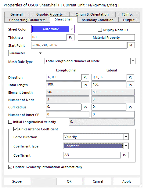
Figure 25.17 Sheet Shell property page [Sheet Shell page]
Sheet Color: Defines the color of sheet.
Display Node ID: If this function is checked, the IDs of all nodes belong to the sheet are displayed.
Material Property: Accesses the dialog box defining the material property of the Sheet. For more information, refer to Material Property.
Thickness: Defines the thickness of the sheet.
Start Point: Defines the starting point of the sheet.
Parameter: Defines the sheet as below parameters
Folding: If Folding is selected, the Point List button is activated. The folding sheet can be defined.
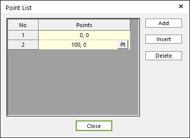
Figure 25.18 Point List dialog box for a folding sheet
Point List: Contains a curve profile in the two-dimensional space as shown in Figure 25.18.
Surface: If Surface” is selected, the Surface Info button is activated.
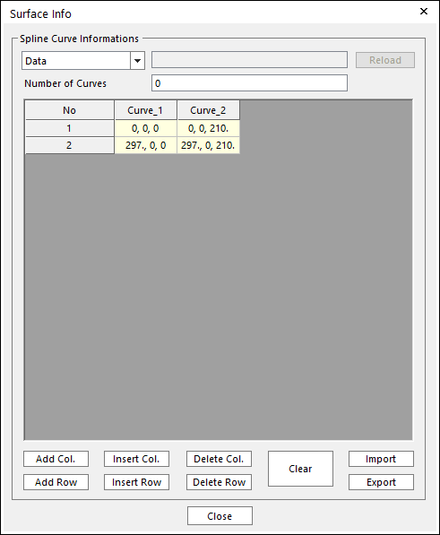
Figure 25.19 Surface info dialog box for a 3D curled sheet
Surface Info: Contains a surface profile in three-dimensional space as shown in Figure 25.19.
Data and File: The surface can be defined from a text file with a matrix file format or hand-written curve profiles. If the surface is defined from a file, the sheet shape can be used as a design parameter during design study or optimization.
Number of Curves: Shows the number of curve profiles
Import / Export: The specified curve profiles can be imported or exported as a text file.
Other buttons: Uses when curve profiles are modified.
Direction: Shows the longitudinal and lateral directions
Total Length: Shows the lengths of the Sheet along two directions.
Element Length: Shows the lengths of a shell element along two directions.
Number of Node: Shows the numbers of nodes along two directions. This can be set when creating the sheet.
Curl Radius: Shows the curve radius of the Sheet along two directions. For more information, click here.
Number of Inner CP: Defines the additional contact points in one rectangular element along two directions. For more information, click here.
Note
Roller Groups with the Check Edge option off and Circular Guide are only supported for this feature.
Initial Longitudinal Velocity: Defines the initial velocity in the longitudinal direction of the Sheet. For more information, click here.
Air Resistance Coefficient: Because the sheet is very light, the dynamics of the sheet is much influenced by the air. The value of air resistance coefficient is the ratio of the resistance force to the kinetic energy of the air in the sheet. The user can select two types of expression and constant. Also user can select the force direction, velocity or element normal.
Force Direction
Velocity : Opposite direction of Velocity for each node.
Element Normal : Opposite direction of element Normal direction.
Expression: Show expression list used for air resistance coefficient.
Constant: Show constant value used for air resistance coefficient
Update Geometry Information Automatically: If this option is unchecked, the position and orientation of the geometry constituting the group are not updated depending on variables in the property page. So, after executing Extract function, this option is unchecked.
25.3.2.1. Material Property
The Material Property dialog box is shown clicking the Material Property button in the Sheet Shell dialog box. The sheet shell supports 3 types of material. For more information, click here. The parameters are explained below.
Isotropic
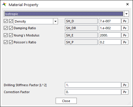
Figure 25.20 Material property dialog box [Isotropic Material]
Density or Total Mass: Defines the density or total mass of the Sheet. For more information, click here.
Damping Ratio: \(\xi\): The structural damping ratio of the Sheet and the damping matrix of \(C\) is computed from the following equation. Its recommendation is a value near 0.008. If you use higher number for a damping, the sheet bending characteristics under dynamical motion can be stiffer.
\(C=\xi \cdot K\)
Young’s Modulus: Defines the young’s modulus of the isotropic sheet.
Poisson’s Ratio: Defines the poisson’s ratio of the isotropic sheet.
Drilling Stiffness Factor: Defines the stiffness in drilling direction of a shell element is multiplied by this factor. This value must be greater than zero. If this value is greater than default value, the solving time can be increased but the relative angle of a node in drilling direction closes to the zero. This function is available in only Sheet Shell.
Correction Factor: Defines the correction factor for bending stiffness of sheet. If the four nodes are not on one plane, the vertical deformation occurs in the plate element of sheet. In this case, the correction factor is used to put the nodes on same plane. The bending stiffness which is computed by Updated Lagrangian methods is multiplied by the correction factor, and then the resultant stiffness is used to calculate an elastic force of a bending term. The value is greater than zero, the sheet become stiffer than original sheet model.
Otrhotropic
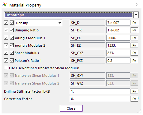
Figure 25.21 Material property dialog box [Orothotropic Material]
Young’s Modulus 1: Defines the young’s modulus of the orthotropic sheet in the longitudinal direction.
Young’s Modulus 2: Defines the young’s modulus of the orthotropic sheet in the lateral direction.
Poisson’s Ratio 1: Defines the poisson’s ratio (\({{{\varepsilon }_{z}}}/{{{\varepsilon }_{x}}}\;\) for uniaxial loading in the longitudinal direction) of the orthotropic sheet. Note that \({{\nu }_{zx}}{{E}_{x}}={{\nu }_{xz}}{{E}_{z}}\)
Shear Modulus: Shows the in-plane shear modulus.
Use User-defined Transverse Shear Modulus: Defines the transverse shear modulus. If this check option is disabled, shear correction factor is used to obtain the transverse shear modulus, which is a default value for original orthotropic material. If checked, user can set the transverse shear modulus.
Transverse Shear Modulus 1: Transverse shear modulus in direction 1 (G1z).
Transverse Shear Modulus 2: Transverse shear modulus in direction 2 (G2z).
Anisotropic
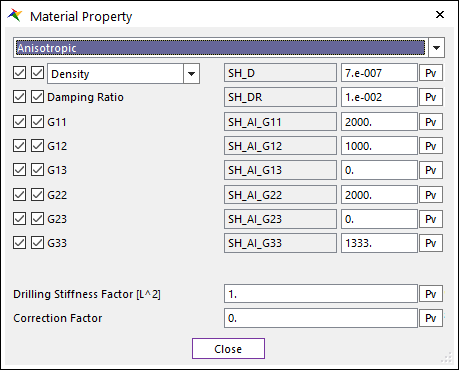
Figure 25.22 Material property dialog box [Anisotropic Material]
G11 to G33 represents the component of constitutive matrix in shell material.