34.1.3.1. Cam Shaft Layout
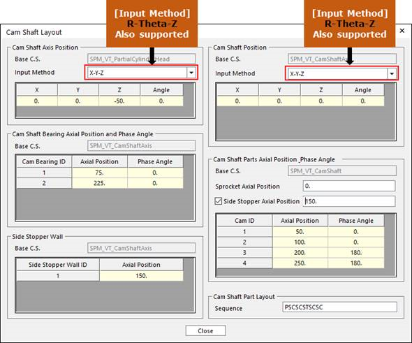
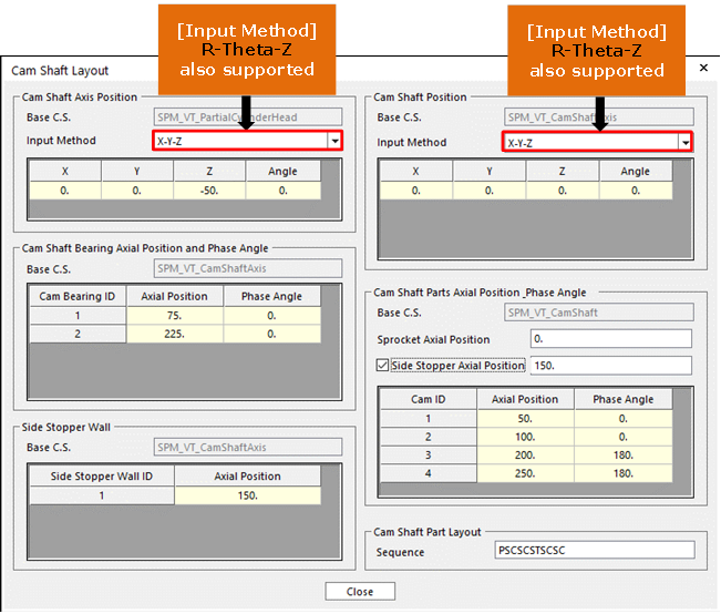
Click Cam Shaft Layout in the Valve Global Data dialog box. And then the user can see the following dialog box.
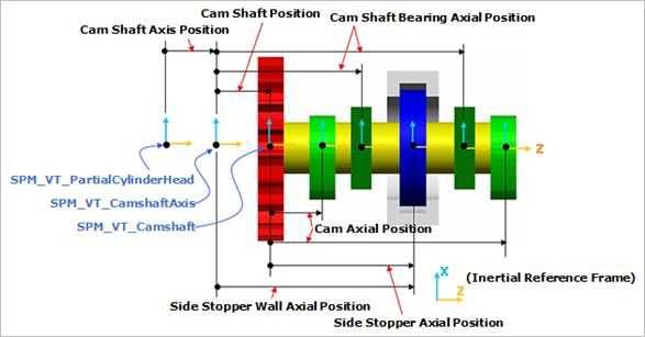
Click Preview Cam Shaft Part Layout in the Cam Shaft Layout dialog box. And then the user can see the following dialog box.
After setting up all parameters, click Close in the Cam Shaft Layout dialog box.