32.3.1.2. EHD Bearing
An EHD bearing is defined between two bodies. The created position types are five:
Engine Block & Shaft Main(EB_SM)
Shaft Pin & Connecting Rod(SP_CR)
Connecting Rod & Piston Pin(CR_PP)
Piston Pin & PisTon(PP_PT)
Engine Block & Balancing Shaft(EB_BS)
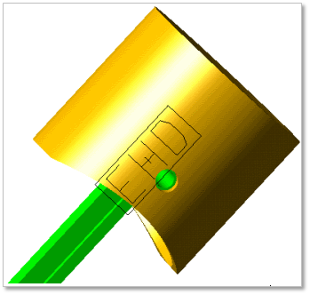
Figure 32.115 EHD bearing
32.3.1.2.1. Modeling Options
Click Rot.Lub icon of the Crank Connector group in the Crank tab. The user can see the Crank Component Bearing – EHD Bearing dialog box.
The user can choose the following types in Component Type and select the position where the bushing bearing is created in Component Index.
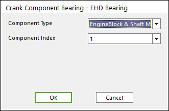
Figure 32.116 Crank component Bearing – EDH Beating dialog box
Click OK.
32.3.1.2.2. Properties
Click the right mouse button on the EHD bearing component to choose Properties of the EHD bearing. The user can modify the property of EHD bearing in the following dialog box.
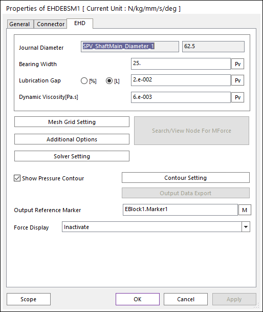
Figure 32.117 EHD Bearing property page
For the modification of EHD bearing, refer to Rotational Lubrication of EHD.
Position information of EHD Bearing
Engine Block & Shaft Main (EB-SM)
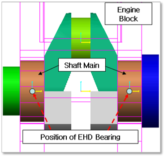
Figure 32.118 Position information of EHD Bearing between Engine Block & Shaft Main
Shaft Pin & Connecting Rod (SP-CR)
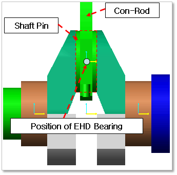
Figure 32.119 Position information of EHD Bearing between Shaft Pin & Connecting Rod
Connecting Rod & Piston Pin (CR-PP)
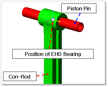
Figure 32.120 Position information of EHD Bearing between Connecting Rod & Piston Pin
Piston Pin & Piston (PP-PT)
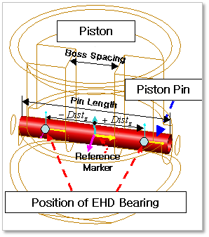
Figure 32.121 Position information of EHD Bearing between Piston Pin & Piston
Engine Block & Balancing Shaft (EB-BS)
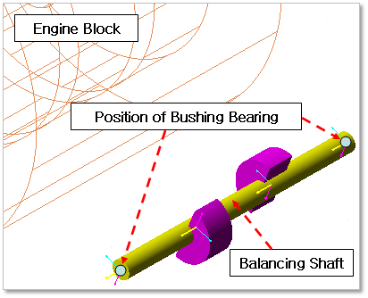
Figure 32.122 Position information of EHD Bearing between Engine Block & Balancing Shaft