10.2.5.1. Create an input File
10.2.5.1.1. ANSYS
This section explains the general process of creating displacement result of ANSYS model through load step files that contain different boundary conditions.
Example
The following example represents how to define an enforced displacement and a static concentrated force for static analysis. Node 1(ID) is fixed for all degree of freedom and translational forces are acting on the node 122.
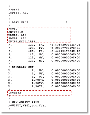
ANTYPE: Specify the analysis type. (0: static analysis )
DDELE: Delete degree of freedom constraints.
FDELE: Delete force loads of nodes.
/OUTPUT, NSOL, OUT,C:\, : Redirect text output to a file(NSOL.OUT) in the path(C:\).
Step to create Displacement output file
In this step, FE model and input file must exist.
Read input file
Select input file that contains user defined boundary and constraint information.
File > Read Input From …
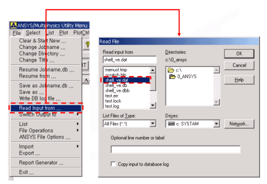
< Read input file >
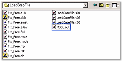
Check created files.
Load Step files are created in the working directory. These files are generated the same as the number of load case.
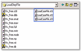
< Check load step file >
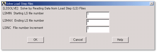
Perform static analysis through load steps
Set Analysis Type
Solution >Analysis Type> New Analysis> Static
Perform Analysis with Load Step file.
Solution > Solve > From LS files
Check output file.
Output file is created in the working directory.
10.2.5.1.2. NX/NASTRAN
This section explains how to generate extra modes in NX/NASTRAN with DMAP command.
Example
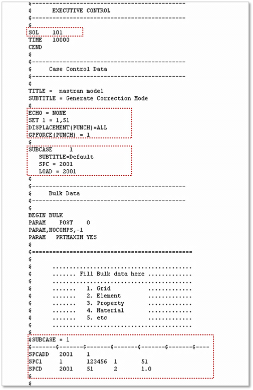
The following example represents how to define an enforced displacement for static analysis. The boundary and load conditions are defined in Case control of DMAP. Node id 1 and 51 are fixed for all degree of freedom and unit displacement is enforced at node 51.
Step to create DMAP command
In this step, FE model must exist.
Solution type
SOL 101: Specify the solution or main sub DMAP to be executed (101: static analysis)
Case control
ECHO = NONE: Include no grid or element information in Punch file.
SET 1: Define grids at which the reaction or applied force is acting.
GPFORCE(PUNCH) = 1: Print the reaction or applied force of the set of grids.
DISPLACEMENT(PUNCH)=ALL: Output displacement for all points in punch file.
SUBCASE: Delimit and identifies a subcase.
SPC: Select set of single-point constraints.
LOAD: Select static loading condition.
10.2.5.1.3. MSC/NASTRAN
This section explains how to generate extra modes in MSC/NASTRAN with DMAP command.
Example
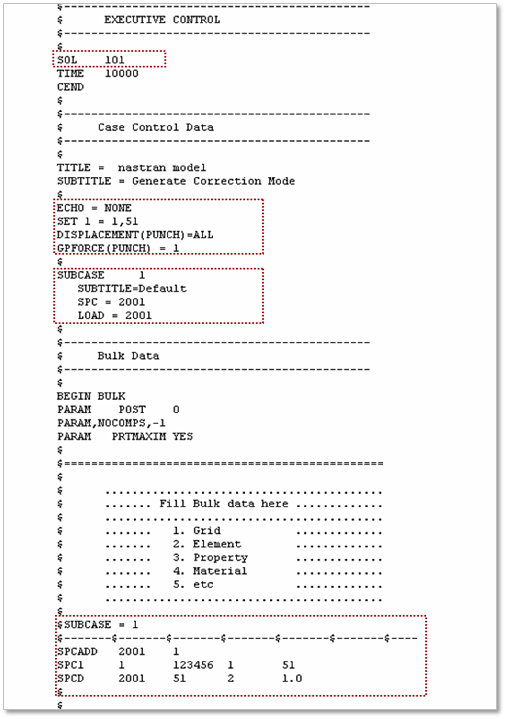
The following example represents how to define an enforced displacement for static analysis. The boundary and load conditions are defined in Case control of DMAP. Node id 1 and 51 are fixed for all degree of freedom and unit displacement is enforced at node 51.
Step to create DMAP command
In this step, FE model must exist.
Solution type
SOL 101: Specify the solution or main subDMAP to be executed. ( 101 : static analysis )
Case control
ECHO = NONE: Include no grid or element information in Punch file.
SET 1: Define grids at which the reaction or applied force is acting.
GPFORCE(PUNCH) = 1: Print the reaction or applied force of the set of grids.
DISPLACEMENT(PUNCH)=ALL: Output displacement for all points in punch file.
SUBCASE: Delimit and identifies a subcase.
SPC: Select set of single-point constraints.
LOAD: Select static loading condition.